EPSON
TITLE
SHEET
REVISION
NO.
SHEETNEXT
F
TM-U295/U295P
Specification
(STANDARD)
18 17
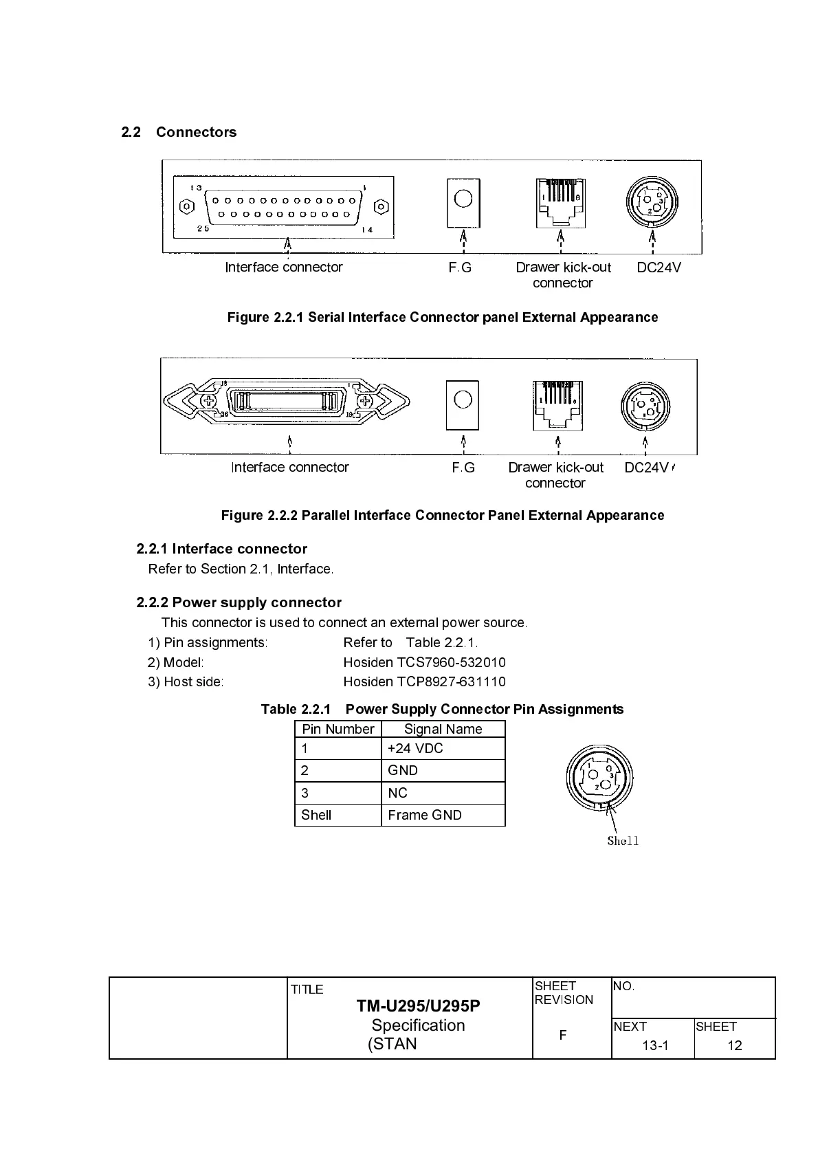
2.2 Connectors
DC24VDrawer kick-out
connector
F.GInterface connector
Figure 2.2.1 Serial Interface Connector panel External Appearance
DC24VF.G Drawer kick-out
connector
Interface connector
Figure 2.2.2 Parallel Interface Connector Panel External Appearance
2.2.1 Interface connector
Refer to Section 2.1, Interface.
2.2.2 Power supply connector
This connector is used to connect an external power source.
1) Pin assignments: Refer to Table 2.2.1.
2) Model: Hosiden TCS7960-532010
3) Host side: Hosiden TCP8927-631110
Table 2.2.1 Power Supply Connector Pin Assignments
Pin Number Signal Name
1 +24 VDC
2 GND
3NC
Shell Frame GND
1213-1