EPSON
TITLE
SHEET
REVISION
NO.
SHEETNEXT
F
TM-U295/U295P
Specification
(STANDARD)
11 10
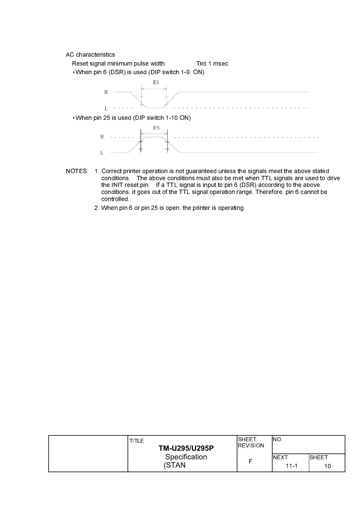
AC characteristics
Reset signal minimum pulse width: T
RS
1 msec
ù
When pin 6 (DSR) is used (DIP switch 1-9: ON)
RS
H
L
ù
When pin 25 is used (DIP switch 1-10 ON)
H
L
RS
NOTES: 1. Correct printer operation is not guaranteed unless the signals meet the above stated
conditions. The above conditions must also be met when TTL signals are used to drive
the INIT reset pin. If a TTL signal is input to pin 6 (DSR) according to the above
conditions, it goes out of the TTL signal operation range. Therefore, pin 6 cannot be
controlled.
2. When pin 6 or pin 25 is open, the printer is operating.
11-1