Maintenance 8. Cable
156 VT Rev.1
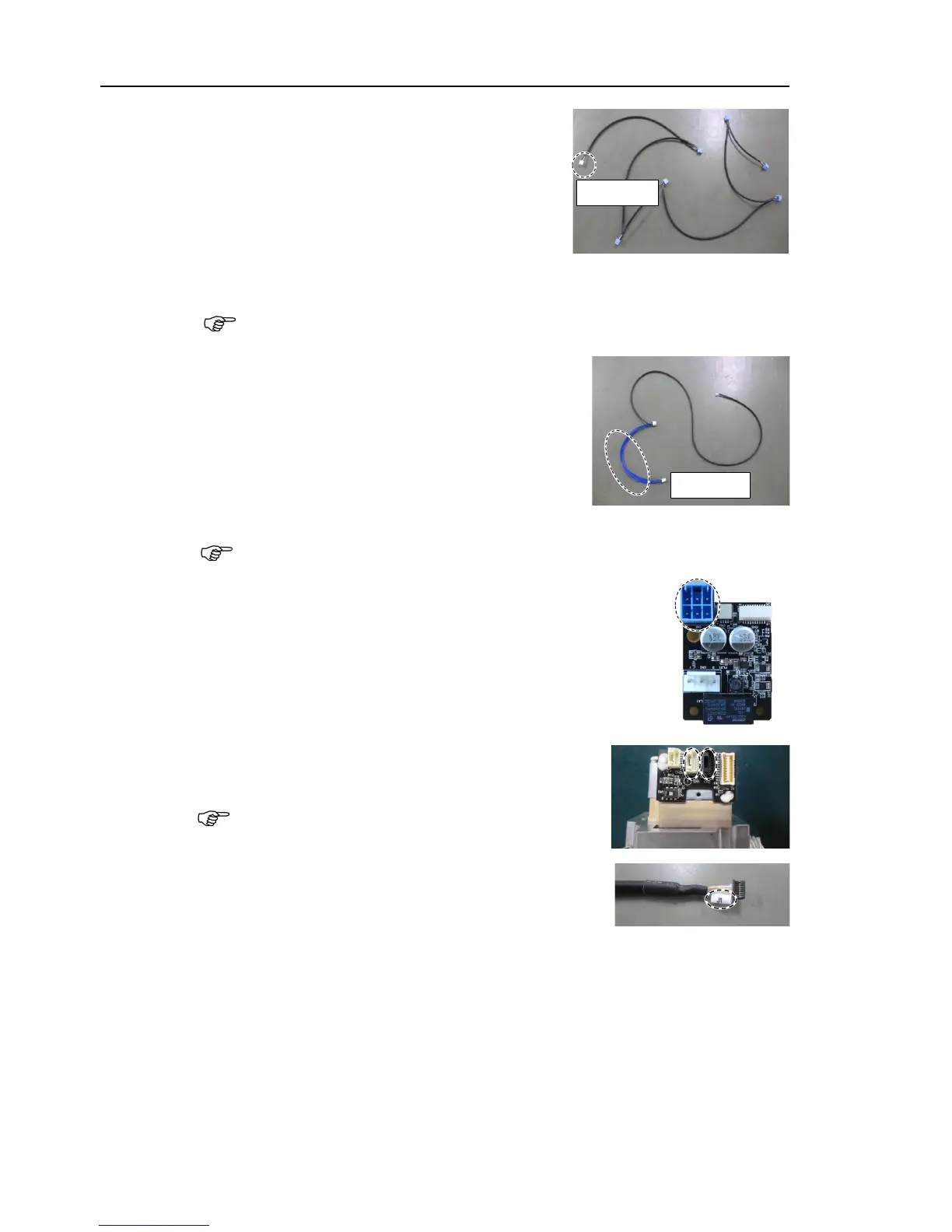
the new power cable in the following order.
Base
→ Arm #1
→ Joint #1 Timing Belt
→ Arm #2
→ Arm #3
→ Joint #4 Timing Belt
→ Arm #4
cables between arms, be sure to pass them through the sleeve of
each joint. The white connecter is the base side.
the new LED cables in the following order.
Base
→ Arm #1
→ Joint #1 Timing Belt
→ Arm #2
cables between arms, be sure to pass them through the sleeve of each
joint. The blue cable is the base side.
Connect the power cable connectors (
int #1, 2, 3, 4,
5, 6 AMP board.
Connect the signal cable connector (for motor) of the
J
oint #1, 2, 3, 4, 5, 6 motor unit.
When passing the cables between arms, be
them through the sleeve of each joint.
marked on the wire marker of the
cable and the joint of the motor unit to be
the same colored connecter is connected to each
. (For the Joint #6 motor, only black colored
the Joint #2 motor.
Reference: Maintenance 10.1 Replacing Joint #2 Motor
the Joint #3 motor.
Reference: Maintenance 11.1 Replacing Joint #3 Motor