Pressure Sensor Installation
The hydraulic pressure sensors are used to measure the lifting load of the telehandler.
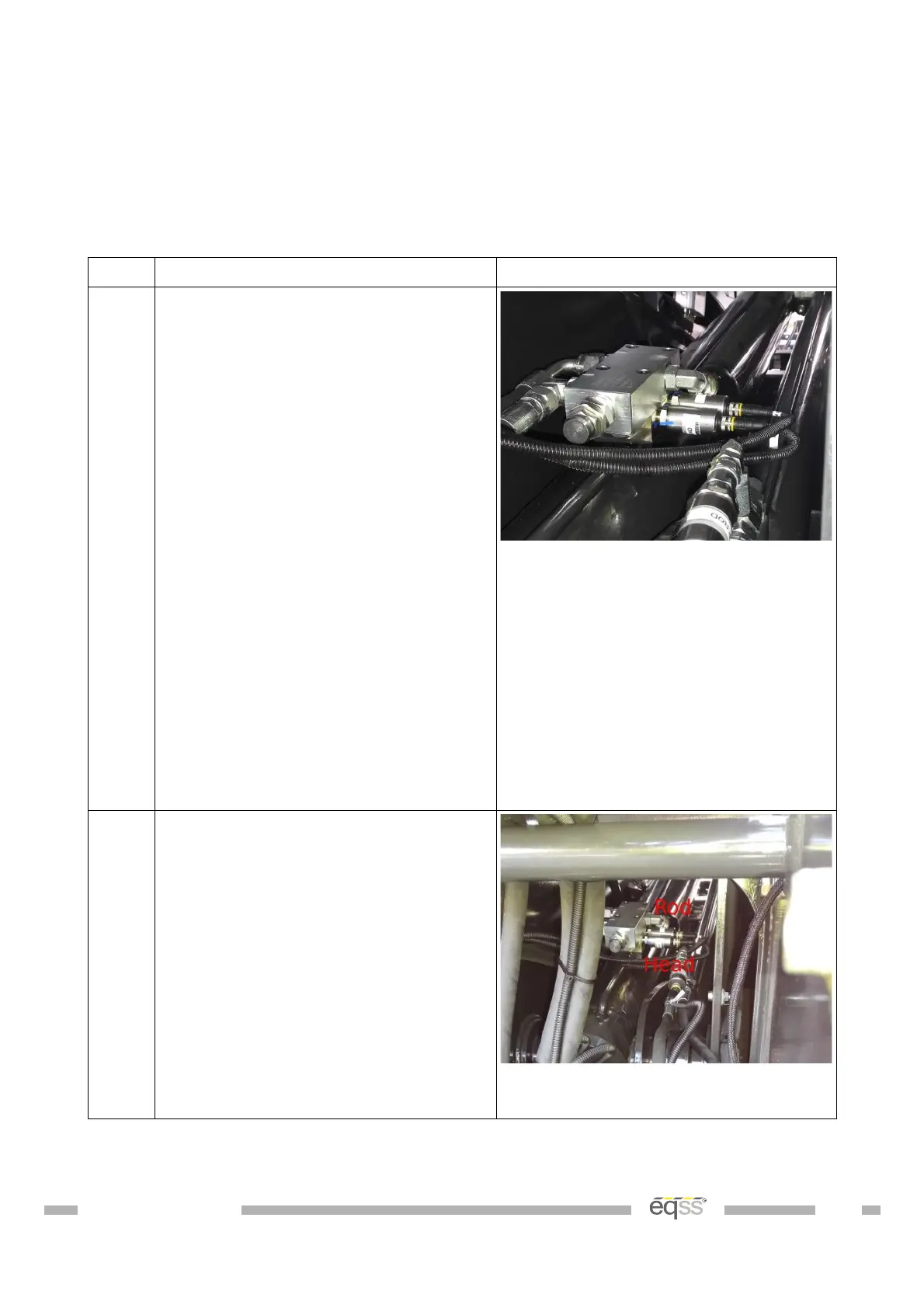
Pressure Manifold
Step Description Diagram
1. Raise the boom to approximately 40
degrees.
Support and secure the boom using
an A Frame or similar apparatus. It
must support at least 2 tons.
Apply the handbrake and insert
chock under wheels.
Remove the counterbalance valve on
the side of the hydraulic lifting ram.
Removing the counterbalance valve
will release the hydraulic pressure
which may result in a spray of oil.
Secure the pressure manifold using
the supplied bolts and seals. Tighten
the 12.9 grade bolts for the manifold
to 41 NM using a torque wrench.
Start the machine, pressurise the
boom and check for leaks.
View from behind the machine
towards the lift cylinder
2. Connect the supplied M12 4 metre
cables (CB001026) into each of the
pressure sensors.
Cable tie to the flexible hydraulic
hoses connected to the main lift
cylinder. Make sure the cable isn't
pinched or stretched when the boom
is raised or lowered.
Run the snake tube and cables
towards the cabin and cable tie with
the other cables during External
Cable Completion on page 28.
View from behind the machine
towards the lift cylinder
Table 5: Pressure Manifold Installation
DO001547 VER: 2303241610 17 of 58
 Loading...