Compensation Pressure Sensors
Step Description Diagram
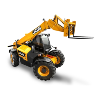
1. Undo the hydraulic connection for
the head compensation into the
manifold block at the rear of the
machine.
Install the supplied tee piece and
pressure sensor in line with the
hydraulic connection.
View from under the boom towards
the rear of the machine
2. Undo the hydraulic connection for
the rod compensation into the
compensation cylinder.
Install the supplied tee connections
with the pressure sensors pointing
back towards the rear of the
machine.
Start the machine, pressurise the
boom and check for leaks.
View from under the boom towards
the rear of the machine
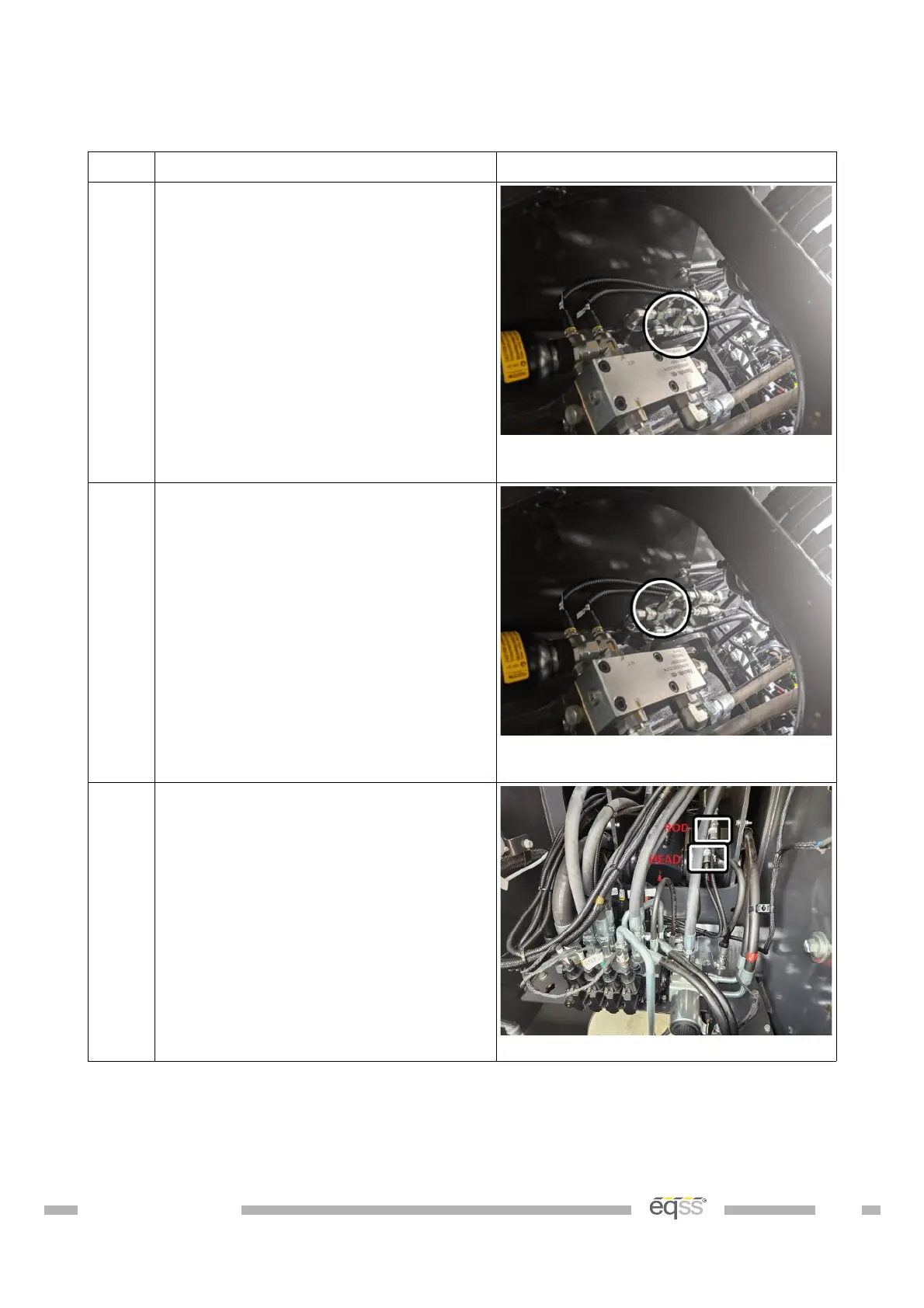
3. Connect the supplied M12 4 metre
cables (CB001026) into each of the
pressure sensors.
Run the cables towards the cabin
and cable tie with the other cables
during External Cable Completion on
page 28.
View from behind the machine
Table 6: Compensation Pressure Sensor Installation
DO001547 VER: 2303241610 19 of 58
 Loading...