Step Description Diagram
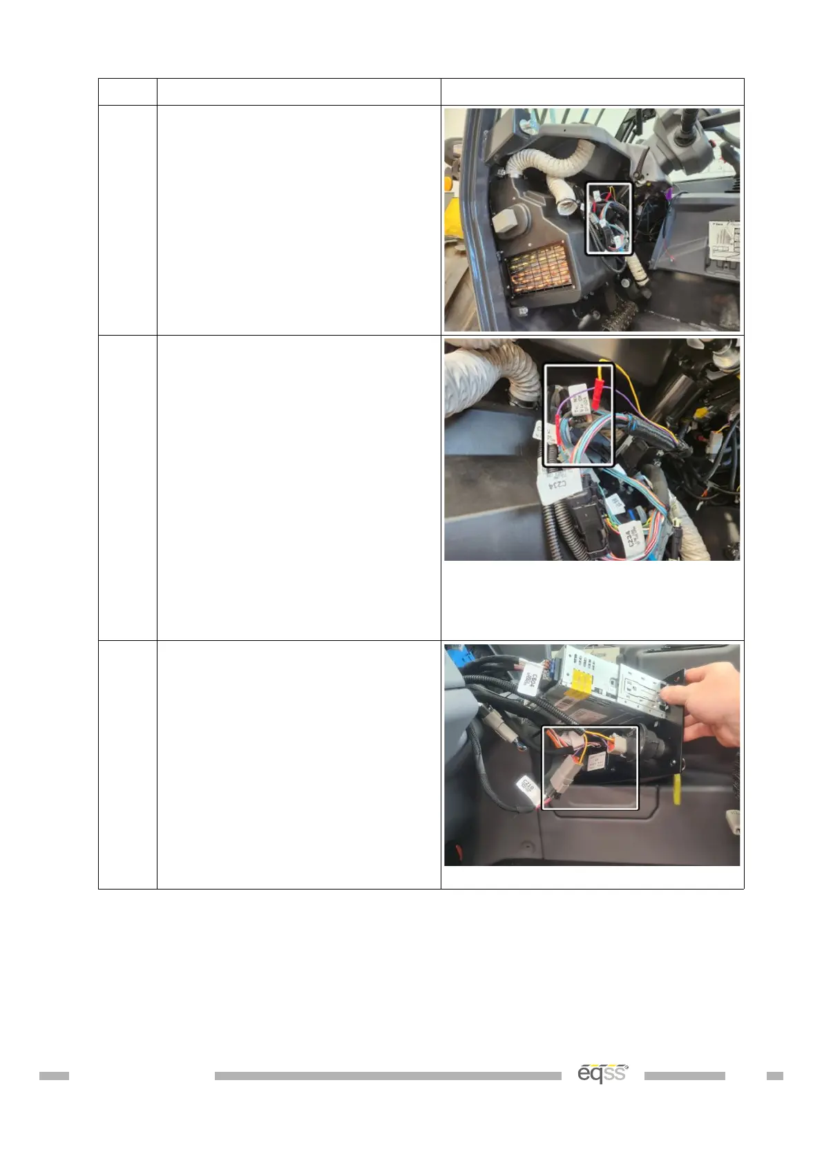
3. Locate connector C234 in the set
of connectors on the harness
running to the steering wheel
switches under the dashboard
panel.
4. Cut the blue wire #3310 and join
the violet wire from the CAN I/O
module to the wire running to the
steering wheel switches.
Join the other side of the wire to
the yellow wire from the CAN I/O
module.
Secure the wire joins with
electrical tape.
View behind the dashboard
Note: The picture above doesn’t
show the electrical tape.
5. Locate the ignition key switch
terminal C210 in the removable
dashboard panel.
Connect the 6 pin tee connection
on the power harness into the
C210 connector.
View behind dashboard panel
DO001547 VER: 2303241610 36 of 58