Step Description Diagram
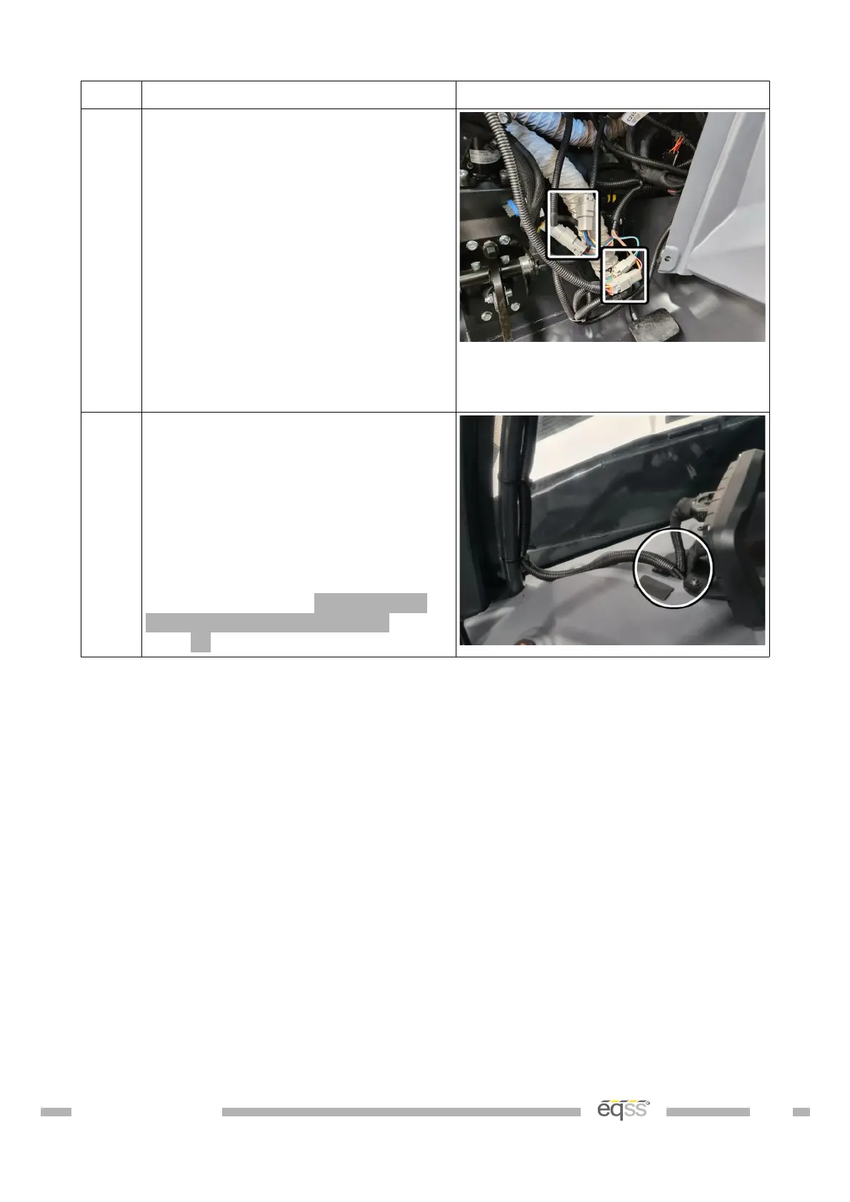
4. Connect the 2 pin connector from
the CAN I/O module harness into the
IO harness.
Connect the 4 pin connector from
the CAN I/O module harness into the
IO harness.
Connect the 6 pin connector from
the machine cutout harness to the IO
harness.
Connect the 12 pin connector from
the lock pin release harness to the
IO harness.
5. Run the 8 pin CCIM cable and the 5
pin user control cable through the
gap between the window and the
dashboard.
Note: The clip-on ferrites will need
to be removed to run the cables
through the gap between the window
and the dashboard. Reattach the
ferrites according to Appendix A:
Attaching Display Connectors on
page 51.
DO001547 VER: 2303241610 39 of 58