8-3 MINI-LINK BAS
EN/LZB 111 0542 P2B Technical Description
N
C
U
N
C
U
N
C
U
N
C
U
N
C
U
N
C
U
C
E
C
E
C
E
C
E
C
E
C
E
C
E
C
E
P
S
U
P
S
U
C
E
L
L
B
U
S
T
E
R
M
E
T
FAN
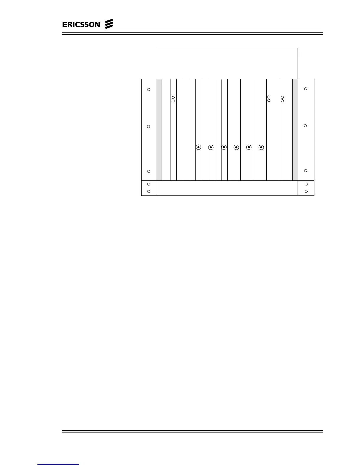
R-AAS
Connection Field
4321171615145 6 7 8 9 10 11 12 13
Figure 8-1 R-AAS with Redundant Power
8.2.1.1 PSU
The function of the PSU is the conversion of central office –48 V
system voltage into 5,15 V and 3,4 V supply voltages and 1,5 V
reference voltage required by the other plug-in units in the R-AAS
(Radio Shelf), and a +56 V supply voltage required by the outdoor
radios and supplied via the coaxial cable connecting, NCU to RAU.
The board is designed for 2-wire or 3-wire distribution, 48 V return is
separated from signal reference ground. Input voltage range: -38,0 V
to –60 V. The PSU also provides inputs for alarm signals from an
external fan unit and an external alarm contact.
The PSU has two front panel LEDs. When the input voltage exceeds
35 V, one of the LED’s is lit. The red LED is lit when any of the
output voltages is below it’s lower tolerance limit, otherwise the green
LED is lit. When the PSU is powered up both LEDs are lit for approx.
1 s, regardless of the output voltages. Maximum output power:
• Shelf boards: 150 W
• Outdoor radios: 150 W
8.2.1.2 Fan Unit
The fan unit, equipped in the R-AAS below the card cage, is the same
module used in the C-AAS (CE Shelf) rear access version, see
paragraph 8.4.5 for more information.