6-3 MINI-LINK BAS
EN/LZB 111 0542 P2B Technical Description
6.2 Management System
This section gives an overview of the control architecture, which the
management system is based upon; information about the possible
interfaces towards higher level systems is available in Paragraph 6.5.1.
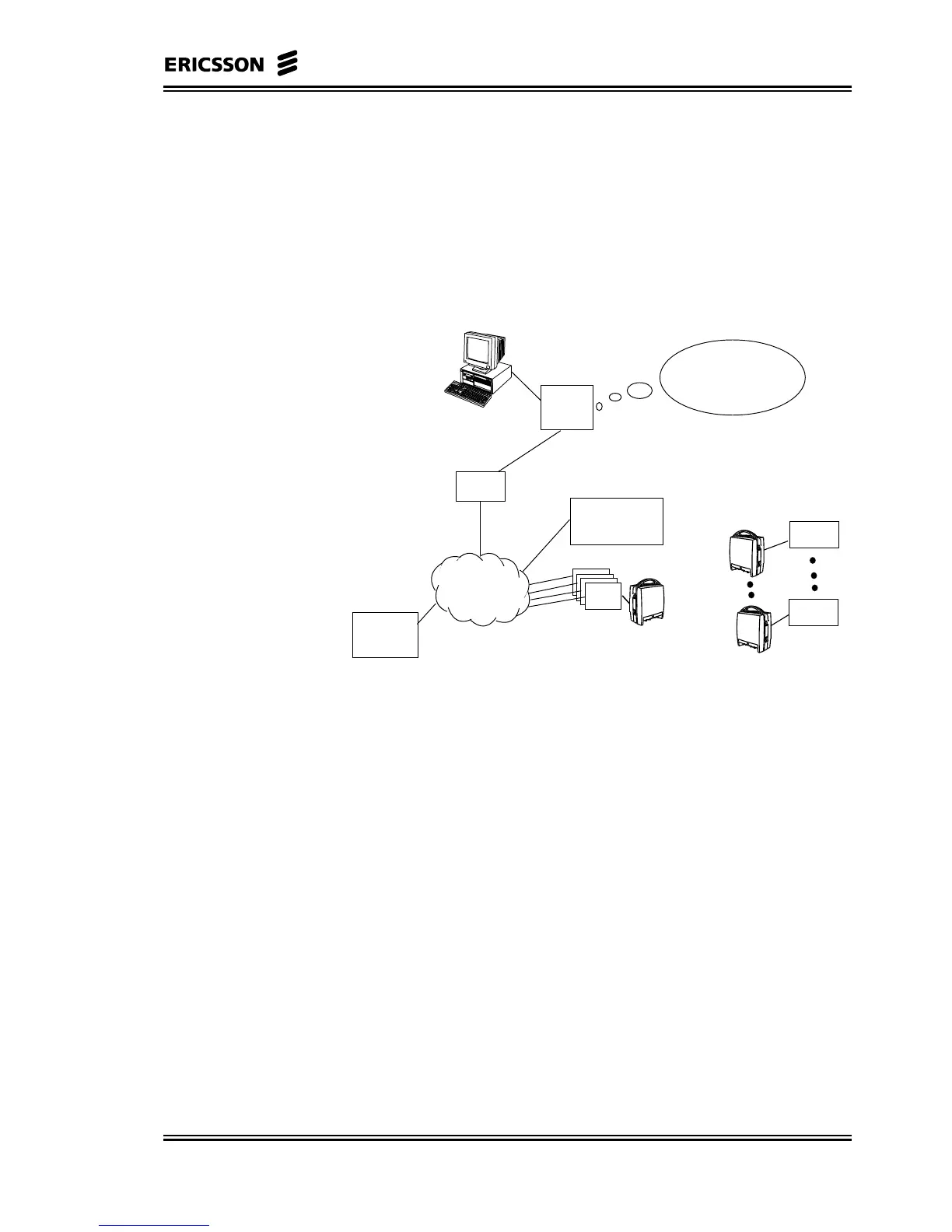
Figure 6-1 gives a general overview of the connections between the
various parts of the network; this figure is used as a reference
throughout this chapter.
EM
CP
ATM
Backbone
Server
Nodes &
Router
Element Manager Service
Configuration, Fault and
Perfomance Management
C-AAS
(CE Shelf)
R-AAS
FlexNU
ATs
FlexNU
Figure 6-1 Management System Architecture
The EM commonly is located in a maintenance centre and
communicates with one or more remote CPs. The CP communicates
with the subtended SNs and AT device/nodes and stores in a database
all the system’s persistent data (for example, configuration data, alarm
logs).
The communications protocol between the EM and the NE is
proprietary. A Simple Network Management Protocol (SNMP)
version 1 interface, using User Datagram Protocol/Internet Protocol
(UDP/IP) over an IEEE 802.3, 10Base2 or 10BaseT, is also supported.
TCP/IP, File Transfer Protocol (FTP) and Telnet are used for file
transfers, for backup and restoration of the database, software releases,
and so on.
If the CP is remote from the EM LAN, the operating company must
provide a Metropolitan Area Network/Wide Area Network
(MAN/WAN) connection for interconnecting the two. The estimated
minimum bandwidth that is needed on the link between EM and CP is
128 Kbps, for a single CP with a single EM user.