MINI-LINK BAS 3-4
Technical Description EN/LZB 111 0542 P2B
The R-AAS is directly connected to the backbone networks, both
ATM and PSTN. CE boards and ET boards can be mixed in a rather
free way in the subrack.
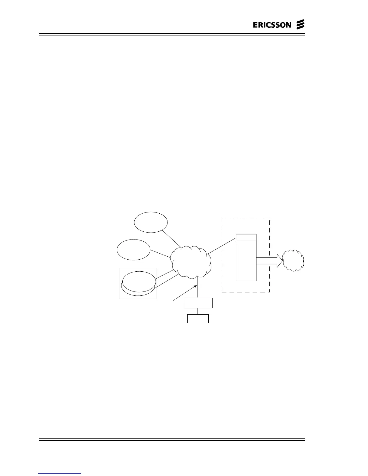
This is the typical SN architecture where mainly data traffic is handled
and only few CE E1/T1 connections are terminated.
In the Figure 3–1 the R-AAS is remotely connected to the CP, through
the backbone ATM network. The local CP connection is supported as
well.
3.2.2 SN C-AAS
The C-AAS SN addresses a specific functionality in a MINI-LINK
BAS network: the termination high number of CE emulation
connections.
The typical application is therefore in large MINI-LINK BAS
networks where several SN R-AAS are present and a high number of
CE connections are transported and terminated within the system.
ATM network
System Node C-AAS (CE Shelf) stand-alone
One PVC for each ETxx,
CE board and NCU
CP
C-AAS
(CE Shelf)
CE boards
ET
PSTN
SN R-AAS
stand-alone
SN R-AAS
stand-alone
SN R-AAS
stand-alone
EM
HUB
HUB
HUB
Figure 3–2 SN C-AAS Stand-Alone
When a large number of E1/T1 connections is terminated within the
system, due to the R-AAS limitations and capacity availability, proper
C-AAS has to be used. All CE traffic coming from each R-AAS can
be terminated in one or a set of C-AAS.
Theoretically, in principle the C-AAS has 16 slots available to host
CE boards for CE traffic collection from the R-AAS through the
backbone ATM network. In practice, the bandwidth budget has to be
analysed when defining the actual structure of this SN.