3-3 MINI-LINK BAS
EN/LZB 111 0542 P2B Technical Description
3.2 SN
The basic MINI-LINK BAS network is constitued by a single R-AAS
and its served access terminals.
This basic network supports all services and can be connected both to
an ATM backbone network and a PSTN network through STM-1, E1,
T1, E3, DS3 interfaces.
A large access network can be made of several basic networks,
according to a cellular deployment. In a MINI-LINK BAS network,
geographically spread, the use of ET1/T1 links for connection of R-
AAS to the PSTN would be quite expensive because of the high
number of links and their length.
MINI-LINK BAS provides an effective solution by the use of a C-
AAS close to the PSTN. Traffic collected from the R-AASs can be
transported toward the C-AASs through a few high capacities STM-1
connections.
This will result in a very cost-effective solution.
The R-AAS and the C-AAS are named, in the Control and
Management perspective, SNs. SNs can be connected to CP and EM
either in local or in remote mode.
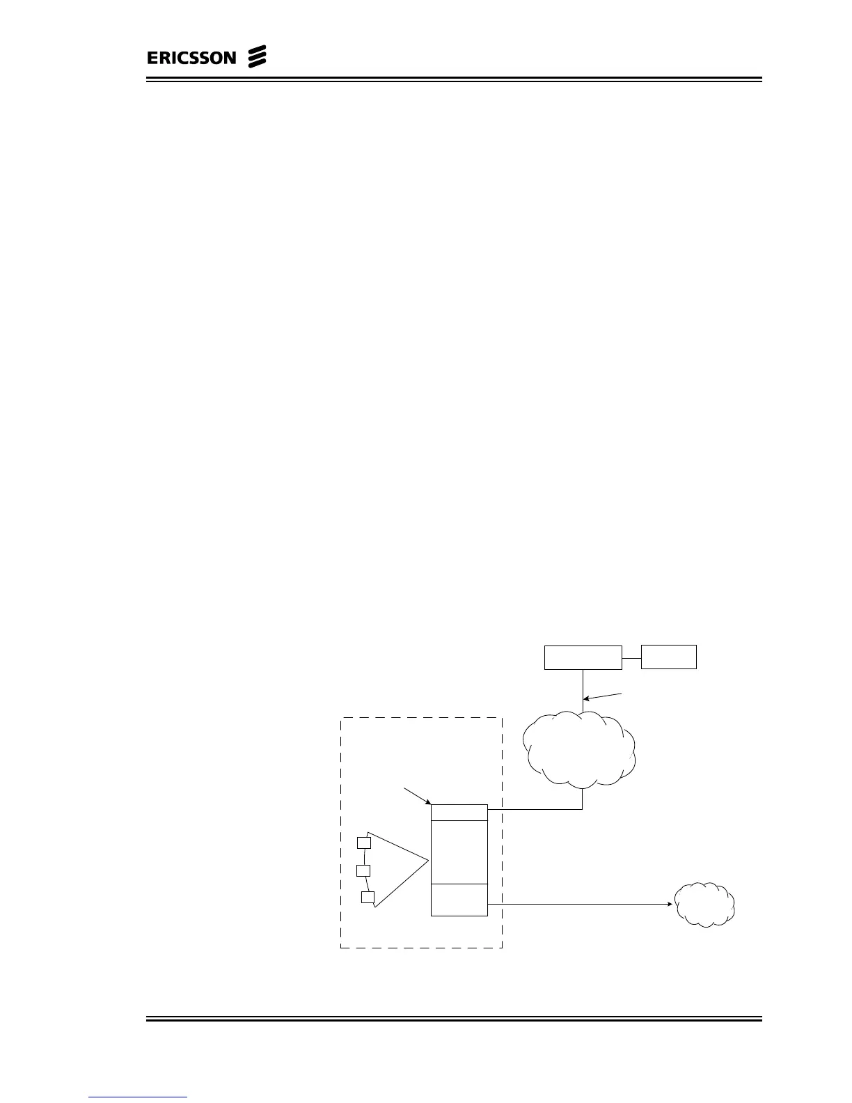
3.2.1 SN R-AAS Stand-alone
This is the basic MINI-LINK BAS configuration made of only one
R-AAS.
ATM network
AT
AT
AT
ET board
R-AAS
Always Slot 1 (CellBus Master)
RN Control Unit
boards
CE boards
System Node R-AAS stand-alone
One PVC for each ETxx,
CE board and NCU
CP
PSTN
EM
HUB
Figure 3–1 SN R-AAS Stand-alone