MINI-LINK BAS 6-6
Technical Description EN/LZB 111 0542 P2B
• Max Burst Size: 30 cells
• Sustainable cell rate:1 cell/5 ms = 200 cells/sec
• Cell Delay Variation Tolerance: 2ms
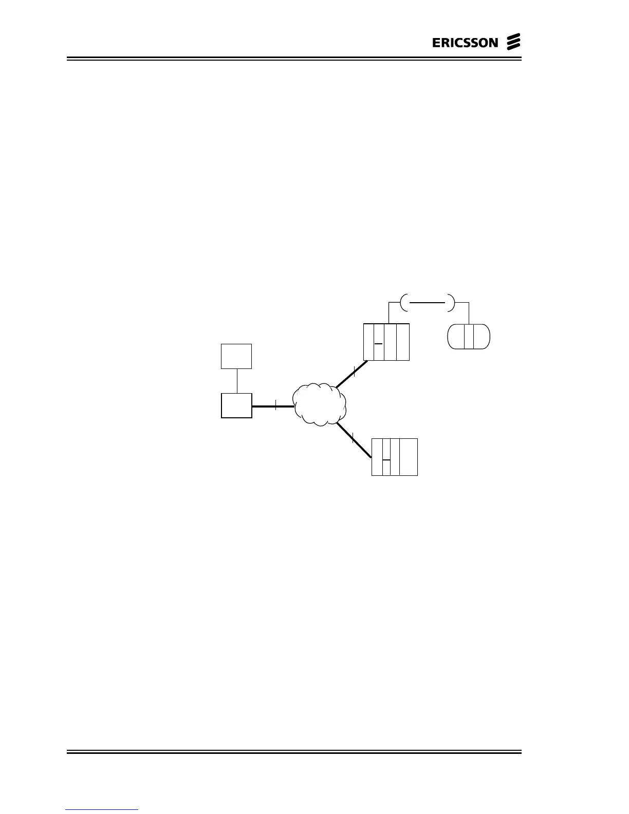
6.3.3.2 Interface Requirements
Two types of interfaces, see Figure 6-4, for the control
signalling are present in the configurations with the CP
remotely located.
• I1 Interface, between CP and ATM switch;
• I2 Interface, between SNs stand-alone and ATM switch.
ATM
EM
CP
ET
ET NCU
C-AAS (CE Shelf)
R-AAS
AT
CE
I 1
I 2
I 2
VPI = 0
VCI = 32 .. 1023
VPI = 1
VCI = 32 .. 1055
Figure 6-4 I1 and I2 Interfaces
I1 Interface
The basic assumptions are:
• VP = 0 out from the ATM adapter
• Maximum number of C-AASs (CE Shelves) is 30
(Subrack number = 2-31; Subrack number = 0 means ‘itself’,
Subrack number = 1 means ‘CP’)
• Maximum number of R-AASs (Radio Shelves) is 224
(Subrack number =32-255).
The values of each board (subrack number and slot) are stored in the
configuration file. The association between the board and the VPI/VCI
information is performed with a process running on the CP, using the
following algorithm: