6-5 MINI-LINK BAS
EN/LZB 111 0542 P2B Technical Description
6.3.2 Board Relay
The board relays are based on channel relaying, with a physical
connection per shelf (1 channel per shelf).
This approach is called board relay and actually means that each DP
behaves as soft relay toward other DPs (lower in the hierarchy) to
exchange control signalling messages without physical connections
with the CP.
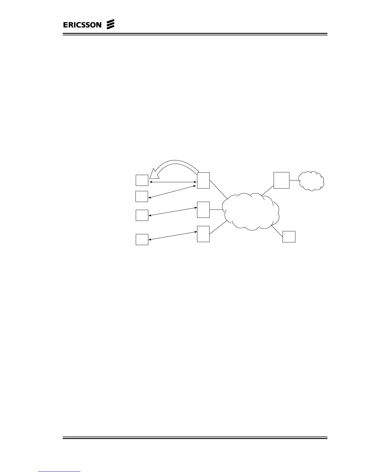
In Figure 6–3, a simple network configuration is shown and the board
relay steps are indicated. As it can be easily verified, the CP needs no
more than one board relay step to distribute control messages to each
DP within the system.
AT
R-AAS
AT
AT
R-AAS
AT
R-AAS
ATM
C-AAS
(CE Shelf)
PSTN
CP
Board Relay Step
Figure 6–3 Board Relay Steps: Correct Configuration
6.3.3 ICS/ATM Connection Rules
The communication between the CP and the DP is realised through
the ATM network, using an Internal Communication System (ICS)
mapped onto ATM cells.
The rules to connect each SN to the ATM switch, with an ATM
connection using VBR service, are distinguished in:
• Configuration requirements
• Interface requirements
6.3.3.1 Configuration Requirements
The configuration data required for the ICS/ATM connections are:
• Peak cell rate: 1 cell/2 ms = 500 cells/sec