MINI-LINK BAS 5-24
Technical Description EN/LZB 111 0542 P2B
5.6 Processing Flow
An overall scheme of the composition both of the downlink and
uplink streams is depicted respectively in the Figure 5-12 and Figure
5-13.
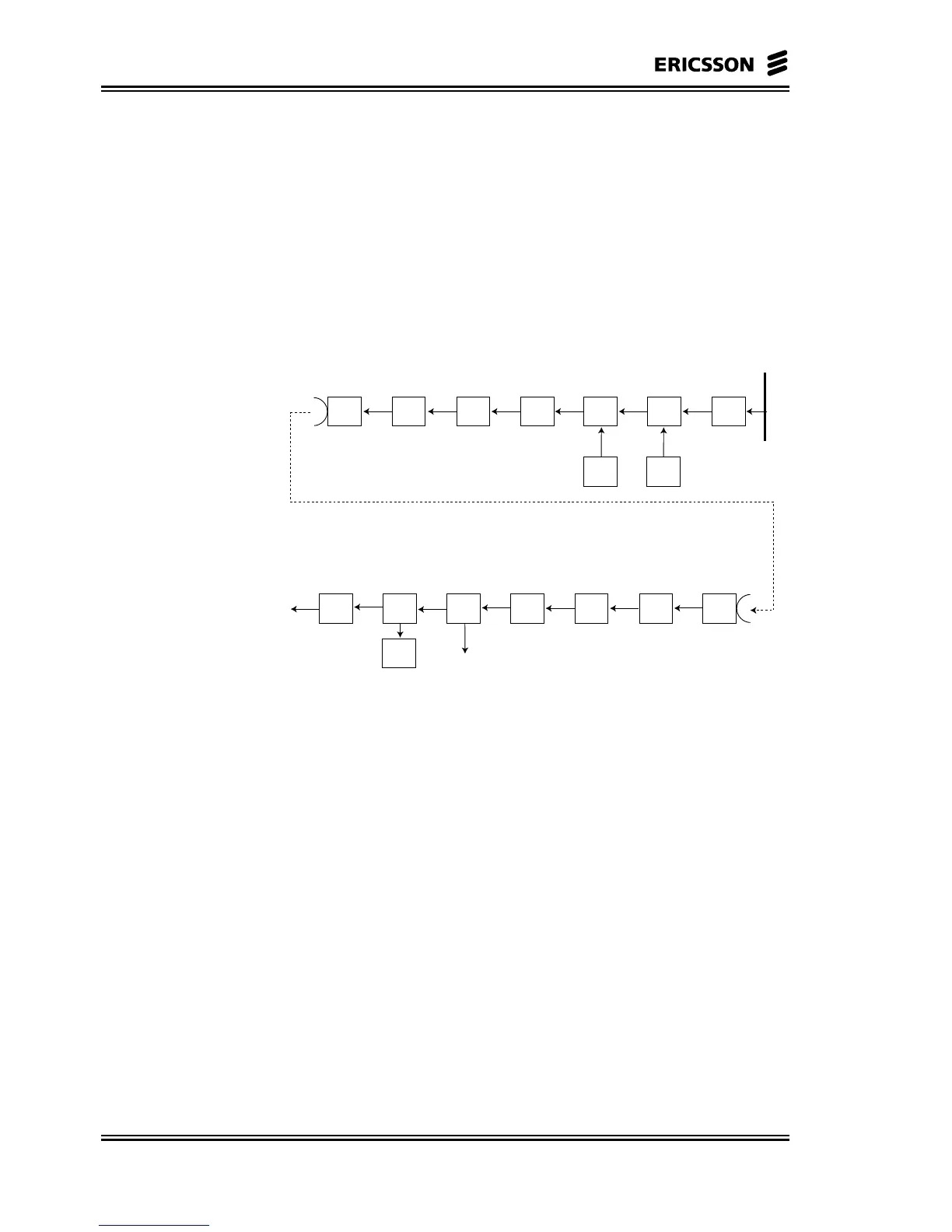
5.6.1 Downlink Processing Flow
RN
Radio
Unit
Modulator FEC Scambler Multiplexer
Cellmux
Port
Backplane
Interface
Framer
MAC
RCC Cells
Permits
User
Radio
Unit
De-
modulator
FEC
De-
scrambler
MAC
De-
multiplexer
ATM
RCC Cells
Permits
Figure 5-12 Block Diagram for the Downlink Stream
In Figure 5-12 the processing flow in the downlink direction is
described.
ATM traffic cells are multiplexed with the ATM cells which transport
the RC information, for modem to modem communication.
ATM cells received from the cellbus interface are buffered until they
can be placed in their proper position in the downlink frame.
There is a separate buffer for system control cells, and these will have
the highest priority in the downstream path.
If no traffic cell is available when required by the generated frame, an
idle cell will be internally generated and put in that position.
In a second step ATM cells are inserted in the slots of the TDM frame
together with MAC permits by the MAC function.
The framer block builds the proprietary TDM frame.
CRC error check fields are added to the downstream signal to allow
for fault handling and performance monitoring.