5-25 MINI-LINK BAS
EN/LZB 111 0542 P2B Technical Description
Finally the TDM Framed data is first scrambled, FEC encoded, in
order to increase transmission robustness, and then modulated.
On the AT side the received data stream is extract realizing the same
operation of the ANT transmission side, but in the reverse order,
moreover data stream is monitored for Excessive Bit Error Ratio
(EBER) after FEC decoding.
When the data stream is descrambled, the MAC extracts the MAC
information and the RC cells and demultiplexing block, the traffic
signal, ATM cells, is available.
At last data is delivered to the ATM handler for ATM layer
processing.
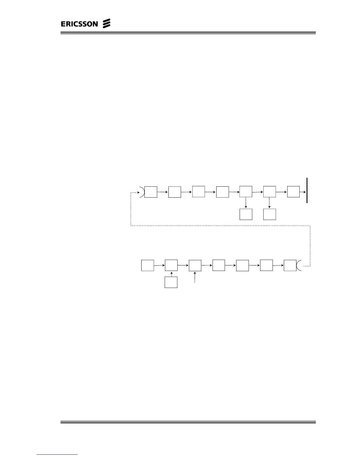
5.6.2 Uplink Processing Flow
Node
Radio
Unit
De-
Modulator
FEC
De-
Scambler
De-
Multiplexer
Cellmux
Port
Backplane
Interface
Framer
MAC
RC Cells
User
Radio
Unit
Modulator
FEC
Scrambler
Framer
Multiplexer
ATM
RC Cells
MAC
Information
Cells
Figure 5-13 Block Diagram for the Uplink Stream
In the figure above the building up of the uplink flow is described in
terms of functional blocks.
The incoming flows of ATM cells are stored in two buffers depending
on the class of service and are multiplexed with the Control cells,
which are queued in a separate buffer and have the highest priority, so
they are inserted in the outgoing frame as soon as possible.
As allowed by sent downlink permits, ATM cells are inserted in the
available TDMA timeslots and sent upstream by the NU.