MINI-LINK BAS 5-10
Technical Description EN/LZB 111 0542 P2B
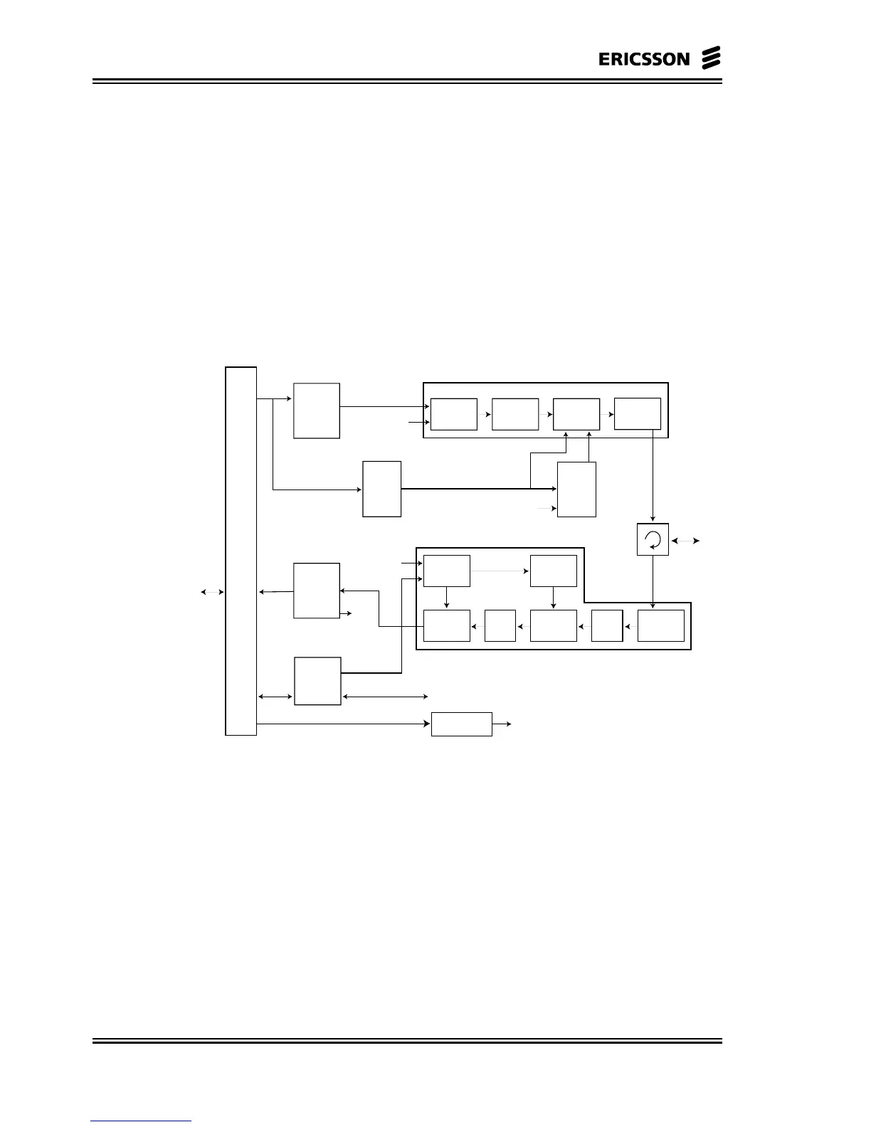
5.3.1 Block Diagram
The following main functions are included in the RAU, as shown in
Figure 5-5:
• Cable interface with lightning protection
• Transmitting IF signal processing
• Receiving IF signal processing
• Supervision and control
• Tx ON/OFF circuit to transmit in burst condition
Transmit IF
Signal
Processing
Frequency Control
Transmitter
Oscillator
Transmitter
Multiplier
& Filter
Final
Amplifier
Branching
Filter
Branching
Filter
Receiver
Oscillator
Multiplier
and
Filtering
AGC
Testport
Frequency
Control
ON/OFF
Switch
Circuit
TX ON/OFF
TX ON/OFF
Output
Level
Control
Output
Level Set
Receive IF
140 MHz
Signal
Down
Converter
Filter &
Amp.
Down
Converter
Receiver
Low
Noise
Amp.
Command
& Control
Signal
Control &
Supervision
Processor
Alarm and
Control
DC/DC Converter
Cable Interface
To
indoor
parts
Receive IF
Signal
Processing
Transmit IF
350 MHz
Signal
To Antenna
Figure 5-5 General RAU Block Diagram
Cable Interface
The incoming composite signals from the indoor units, that are, the
transmitting IF signal, command and control signal and DC, are
demultiplexed in the cable interface and forwarded for further
processing:
• Transmitting IF signal: modulated signal with a nominal
frequency of 350 MHz
• The command and control signal from modem to RAU: an ASK
modulated signal with a nominal frequency of 6.5 MHz;