MINI-LINK BAS 2-10
Technical Description EN/LZB 111 0542 P2B
• From a RN to a ATM switch, through an ET155 interface board;
OC-3/ STM-1 (User to Service connection)
• From a RN to a PSTN switch, through a CE-SNI E1/T1 interface
board (User to Service connection)
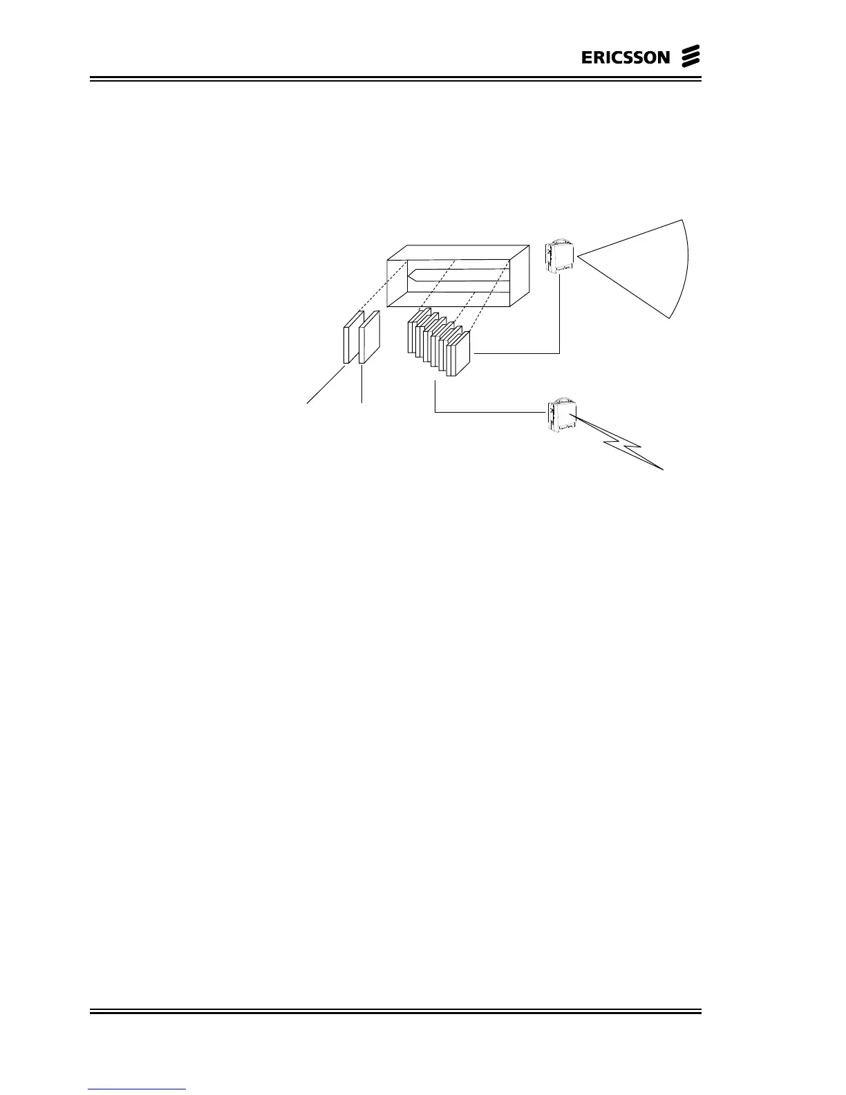
Point-to-multipoint
connections
Point-to-point
connections
Node
Control
Unit(s)
CE_SNI_E1/T1
SDH/SONET/ATM
Cell-BUS
Radio Shelf
Figure 2-6 R-AAS
The interfaces at the customer premises, in our case at the ATs, are
referred as User interfaces, whereas interfaces toward backbone
network are referred as Service interfaces.
Subscriber traffic can be connected in a User to Service connection,
from the subscriber to the backbone network, or from User to User.
For User to Service connections, CE traffic from various RN, can be
terminated in the R-AAS using the CE-SNI (E1/T1) board. As an
alternative it can be connected through an ET155 to an ATM network
and then terminated in an external C-AAS (CE Shelf) using CE-SNI
(E1/T1) boards or in other equipment supporting standard CE
termination functions.
Data traffic related to an AT Ethernet interface, similarly, can be
connected in a User to Service connection from the RNs through an
ET155 to an ATM switch. For User to User connections (data or CE),
the R-AAS provides a through path from RN to RN.
2.2.2.2 ODU
ODU contains Node Antenna and Radio. The ODU is connected to the
NCU through a coaxial cable.
The Node Antenna used for point-to-multipoint applications is sector
antenna, highly directive in elevation. For point-to-point applications
the antenna that is used is a directive ”Low Profile” parabolic type
antenna.