2-9 MINI-LINK BAS
EN/LZB 111 0542 P2B Technical Description
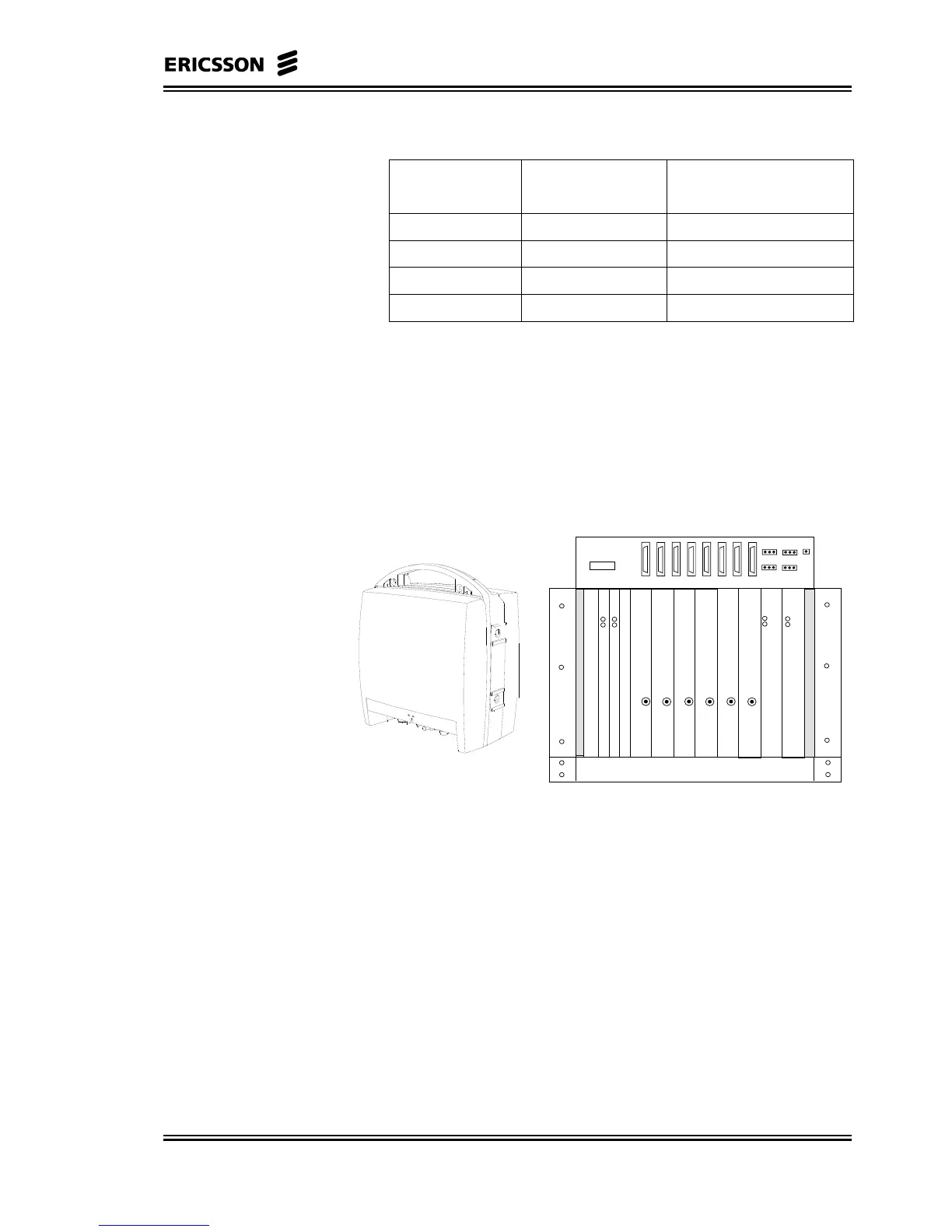
R-AAS can support different configurations:
Number of RNs
Number of CE
boards
Number of E1/T1
interfaces
62 8
54 16
46 24
3, 2, 1 8 32
In principle, a fully equipped R-AAS with 6 RNs, could cover up to 6
* 64 = 384 ATs. However, in order to optimise the overall
performance of the system, it is recommended not to exceed 128 ATs
per R-AAS.
The R-AAS backplane can handle up to 530 Mbps, providing cross-
connect functionality between ATs covered by RNs inserted into the
same R-AAS.
P
S
U
P
S
U
FAN
R-AAS
SUB-ID
TX/RX
SLOT2
TX/RX
SLOT3
TX/RX
SLOT4
TX/RX
SLOT5
TX/RX
SLOT6
TX/RX
SLOT7
TX/RX
SLOT8
TX/RX
SLOT9
Figure 2-5 ODU and the R-AAS
R-AAS provides an ATM cross-connection capability through a
distributed bus architecture named Cellbus. Each NCU, ET, CE-SNI
boards access the bus through a CUBIT-PRO device.
ET board in slot 1 will acts as bus arbiter.
The traffic from the NCU/RNs is cross connected on the Cellbus to
allowing very flexible interconnection between two ATs in a RN.
ATs can be connected not only to the backbone networks but also
among them:
• ATs in a RN (User to User connection)
• From one RN to another RN (User to User connection)