MINI-LINK BAS 2-8
Technical Description EN/LZB 111 0542 P2B
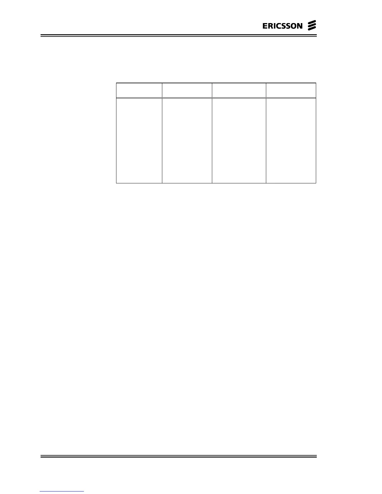
Moreover some capacity is allocated for control purpose and Physical
Layer preservation. In the table are reported the max number of
unstructured E1/T1 connections versus the number of ATs.
ATs/RN UF (%) E1/RN T1/RN
1 to 8 0.96 14 18
9 to 16 0.93 13 18
17 to 24 0.90 13 18
25 to 32 0.87 13 17
33 to 40 0.84 13 17
41 to 48 0.81 12 17
49 to 56 0.78 12 16
57 to 64 0.75 12 16
2.2.2.1 R-AAS
The R-AAS is an indoor mounted subrack that can accommodate up
to six plug-in NCUs (Modem + MAC). Each NCU is connected to an
ODU, which is dedicated to a RN in a sector.
R-AAS can also house ET and CE-SNI boards. ET boards provide
Wide Area Network (WAN) connectivity towards ATM backbone, IP
router, C-AAS. CE-SNI boards provide connectivity towards PSTN.
R-AAS provides a total of 17 board slots, which are distributed
according to the following scheme.
• Slot 1: ET board, any type 155, 45 or 34 Mbps
An ET board shall be always present for Cellbus
arbitration.
• Slot 2, 3: 2 CE-boards
• Slot 4, 5: 1 NCU or 2 CE-boards
• Slot 6, 7: 1 NCU or 2 CE-boards
• Slot 8, 9: 1 NCU or 2 CE-boards
• Slot 10, 11: 1 NCU
• Slot 12, 13: 1 NCU
• Slot 14, 15: 1 NCU
• Slot 16: POU
• Slot 17: POU
Depending on the configuration, a R-AAS can host up to 6 RNs, or up
to 8 CE-boards that can terminate 32 E1/T1 interface connections.