2-7 MINI-LINK BAS
EN/LZB 111 0542 P2B Technical Description
A RN, equipped with a sector antenna, creates a sector carrier that
typically covers an area up to 6 km in radius. Multiple sector carriers
can be used to increase the capacity within a sector and multiple
sectors can be used to cover a complete cell area of a Radio Hub.
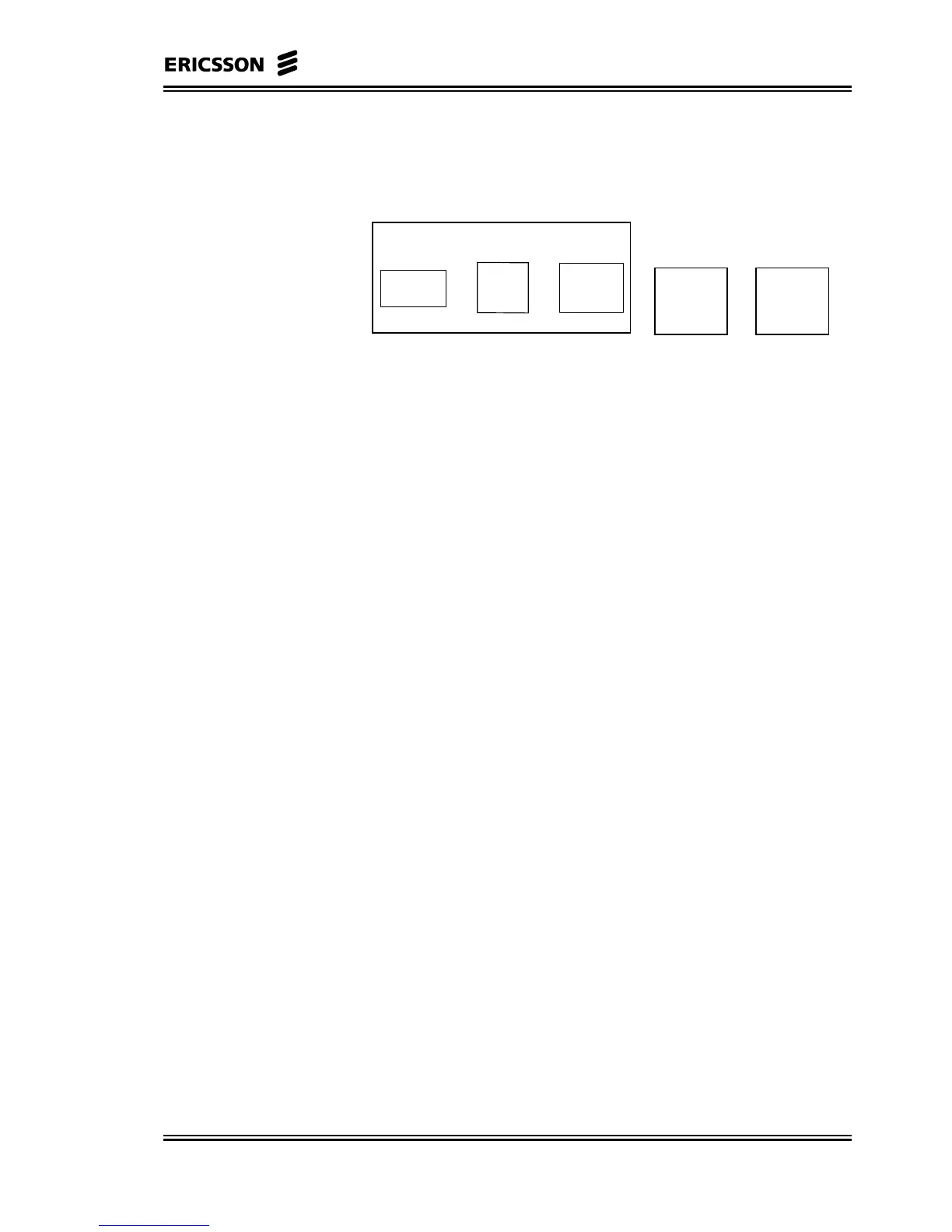
Node
Control
Unit
Node
Radio
Unit
Node
Antenna
Radio Node (RN)
=
Node
Control
Unit
MAC
+
Modem
Figure 2-4 RN Block Diagram
The Node Antenna and the Radio are encased in a weatherproof
outdoor mounted casing. The Radio is highly integrated and connected
to the IDU via an Intermediate Frequency (IF) coaxial cable.
The microwave parts incorporate Ericsson’s unique Microwave
Monolithic Integrated Circuit (MMIC) technology that supports
integration of a complete receiver and transmitter into a single multi-
chip module, thus reducing the size of the ODU (see Figure 2-5).
MMIC technology also guarantees extremely high reliability and is
suitable for high-volume production.
The IDU is the NCU of the RN and it consists of Modem and MAC
board sandwiched in a single plug-in unit.
The Modem board provides the IF interface towards the outdoor
mounted radio and contains all modulating/demodulating functions.
The Modem is also in charge to maintain the radio links, providing
control loops for frequency, timing and transmitter power.
MAC functionality rules the traffic demands toward and from the
ATs. MAC is based on very fast protocol and scheduling mechanism
that grant capacity request in less than 1 msec.
The F-DCA feature of the MAC protocol affords very high statistical
gain so that Radio capacity is used in a very efficient way.
The MAC board connects to the ATM bus on the backplane of the R-
AAS.
The downering cell rate managed by a RN is 78000 cells/s. This is a
net capacity in downlink and a gross capacity in the uplink.
In order to calculate the net capacity in uplink it must consider the
overhead, which is necessary to handle traffic queues status in each
AT. The overhead depends on the number of ATs per RN and on the
polling period.
In the following table the capacity reduction is given for a default-
polling period, 80 slots, versus the number of ATs per RN. The
Uplink Efficiency (UF) varies from 0.96 to 0.75.
The throughput at the application level, both CE and Ethernet will
decrease because of the ATM and AAL1, AAL5 overhead.