4-7 MINI-LINK BAS
EN/LZB 111 0542 P2B Technical Description
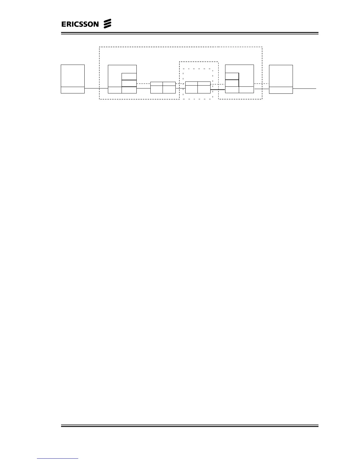
Higher Layers
PHY
End User
equipment
AAL-1
ATM
PHY
(RADIO)
PHY
Mapping Function
ATM ATM
PHY
(RADIO)
PHY
(SDH)
R-AAS
S
Permanent Virtual
Connection
MINI-LINK BAS
Ethernet 10base T
ATM ATM
PHY
(SDH)
PHY
(SDH)
AAL-1
ATM
PHY
PHY
(SDH)
Mapping Function
ATs
C-AAS
(CE Shelf)
Higher Layers
PHY
Operation
equipment
Ethernet 10base T
ATM
Node
Figure 4-4. OSI Model for Transparent Transport of E1/T1 Data in
MINI-LINK BAS
The delay on CE traffic is due mainly to four contributions:
• ATM packetization delay
• MAC delay
• Transport delay
• Cell delay variation compensation delay
The ATM packetization delay is related to the time needed to fill one
ATM cell with the CE data. In the E1 and T1 case this value is equal
to 183 and 244 µs respectively.
The MAC layer in the MINI-LINK BAS introduces a delay of the
order of 1 ms. The transport of cells over the air is of the order of 0.1
ms depending on the actual location. Its contribution to the total delay
is therefore insignificant.
The Cell Delay Variation compensation delay is inserted at the
receiving side to guarantee that there are not octet starvations in
rebuilding the E1/T1 signal due to high cell delay variation. Typical
values are of the order of 2 ms.
The delay for unstructured CE traffic is therefore of the order of 3 ms.