10
B
Creating the Cavity
B1 Cavity Shape
The DS1400 is suitable for timber framed cavities.
Most existing masonry cavities will not be suitable.
B2 Designing the Cavity
The following aspects must be considered when designing this installation:
• Appliance physical size
• Single sided or Double sided
• Wall finishing and interaction with appliance
• Positioning of appliance in regards to wall lining (depth into wall)
• Is a Fascia to be used? one side or two sides?
• Exhaust termination aspect – horizontal / vertical and flue configuration
• Flue exhaust fan noise
• Exhaust cowl access for maintenance
• Gas pipe layout
• Gas isolation valve / pressure test point position
• Electrical isolation switch
• Home automation network connections - Ethernet cable layout
The cavity and wall linings may be constructed from standard timber framing materials and do not need
to be non-combustible.
Do not line the top of the cavity.
It is not necessary to line the sides, or back of the cavity.
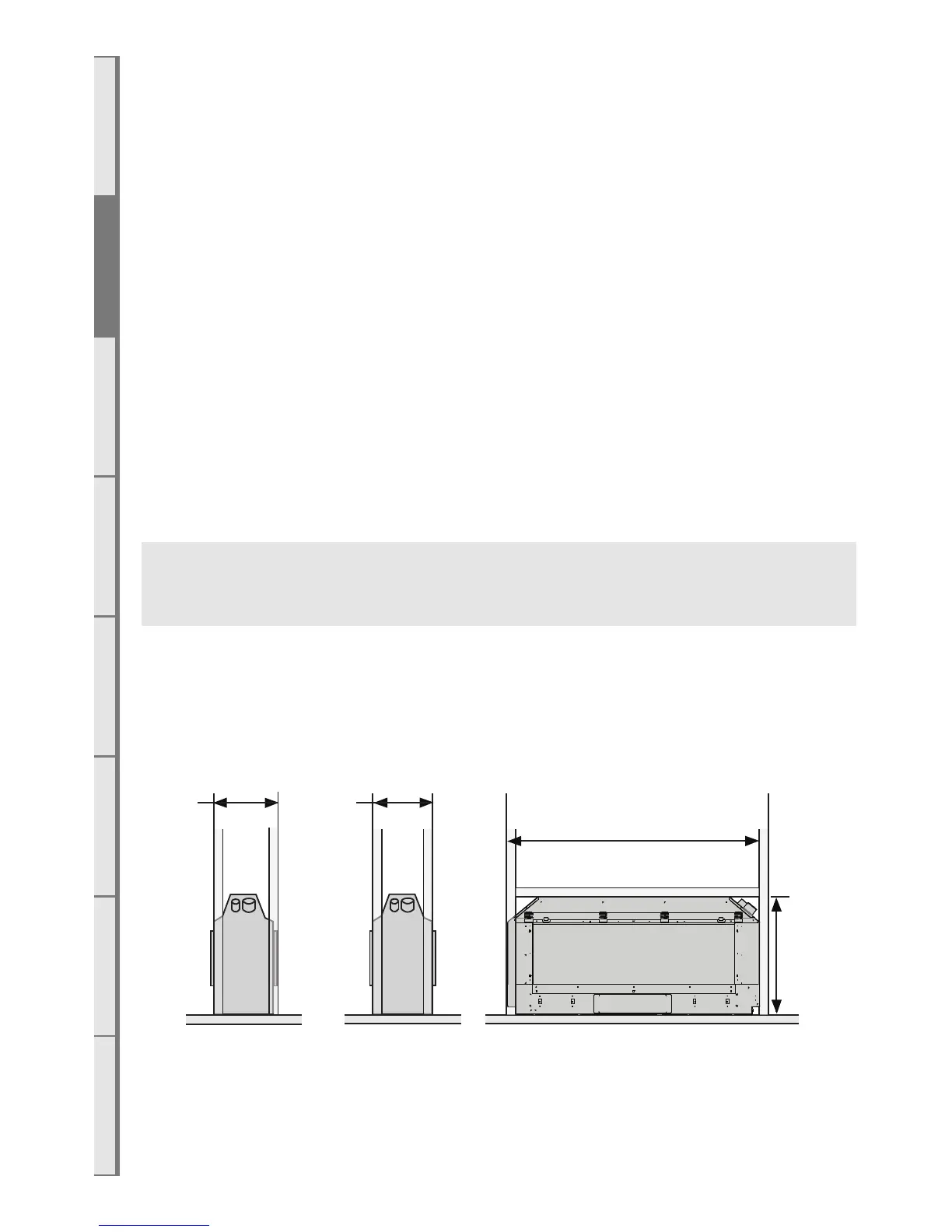
Minimum Framing Dimensions
This DS1400 fire is to be installed prior to any wall lining.
The wall lining is the very last task to be completed in this installation.
350
min*
1700 min*
Side
Single Sided
Side
Double Sided
Front
364
min*
850
min*
*Dimensions shown do not include allowances for
clearance to combustibles to the ue