25
D
Installing the Electricity and Gas to the Appliance
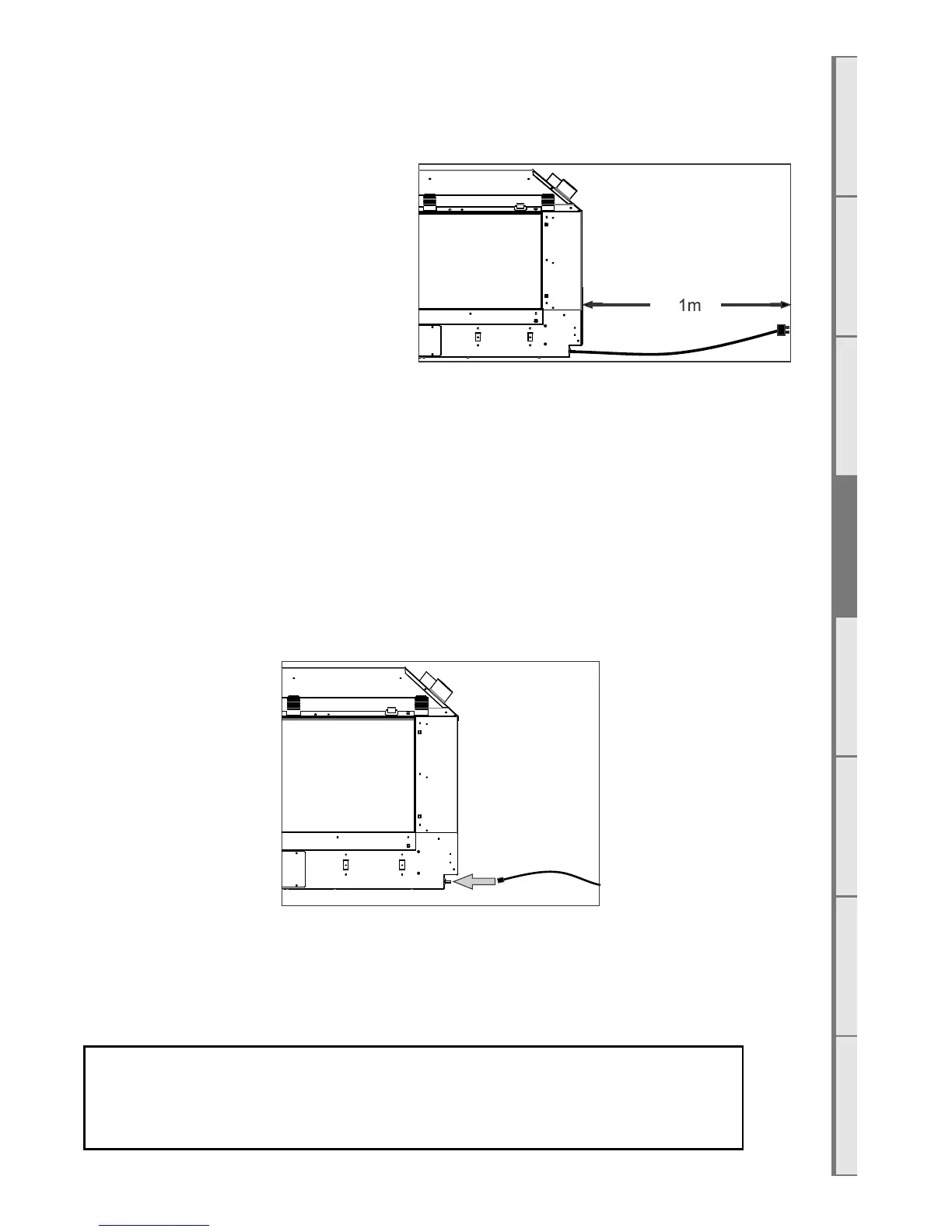
D1 Power Supply
While the cavity is being created consideration
should be given to appropriate location of a
standard 3 pin, EARTHED 230/240V power
outlet. This must be within 1.0m of the bottom
right of the appliance.
IMPORTANT: Locating the power outlet
within the cavity makes the installation very
neat but provision MUST be made to be able to
switch the power supply o and on (electrical
isolation switch) and MUST be accessible after the heater has been installed. This is normally done by
means of a separate switch located outside of the cavity and wired to the plug. This will allow techni-
cians to isolate the power supply before servicing the appliance.
This appliance must not be located immediately below a socket outlet.
This appliance will draw a maximum of 2 Amps from a 230/240V supply.
No additional power supply is required for the power flue.
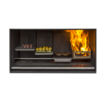
D2 Network Cable
A 5 metre length of network (Ethernet) cable has been supplied. Connect it to the appliance (lower
right) and the buildings modem.
Two network cable access points are available: the primary connection is on the bottom of the RH out-
er face of the appliance for connecting permanently to the buildings router, the secondary connection
point is located where the AUX button can be found (shown in section E9), for service technicians to
access when the main connection method has not been used and has become inaccessible.
If you do not wish to connect the fireplace to the modem, the Network /
Ethernet cable should be run to somewhere accessible by a service
technician, such as a cupboard.