SuZhou Eshine Elevator Components Co., Ltd. Chapter 2 Installation and Wiring
YS-K01 Door Controller User Manual ―5―
DPA Door position signal output
terminal
DPA,CME normally open
PAC Output signal ground Isolated from input ground COM
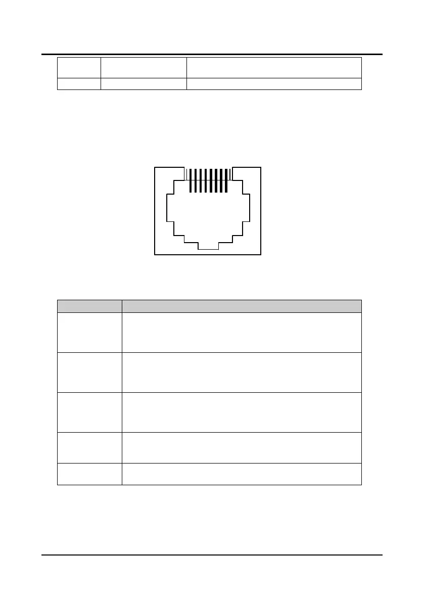
2.1.5 Panel Interface Description
The controller can be connected to the optional special panel (YS-P01, YS-P02 or YS-P03)
through RJ45 interface by general network wires. It can be used for the user parameter settings,
copy and operation monitoring state etc. RJ45 interface is described as Figure 2-2.
Figure 2-2 Panel interface
2.1.6 State Indicator Description
Symbol Description
PC1-LED (green)
Set the open-door arrival as normally open contact and the indicator is off. When
open door arrives, the indicator will be on
Set the open-door arrival as normally closed contact and the indicator is on.
When open door arrives, the indicator will be off
PC2-LED (green)
Set the closed-door arrival as normally open contact and the indicator is off.
When closed door arrives, the indicator will be on
Set the closed-door arrival as normally closed contact and the indicator is on.
When closed door arrives, the indicator will be off
DPA-LED (green)
Set the door position signal as normally open contact and the indicator is off.
When position arrives, the indicator will be on
Set the door position signal as normally closed contact and the indicator is on.
When position arrives, the indicator will be off
RUN-LED (green)
When the controller is not in running state at power on (standby), indicator will be
on
When the controller is in running state at power on, indicator will be flashing
FAULT-LED (red)
When the controller has fault, indicator will be on
When the controller has no fault, indicator will be off