ETAS Hardware Description
ES930.1 - User Guide 20
3.4 Overview of Function Groups
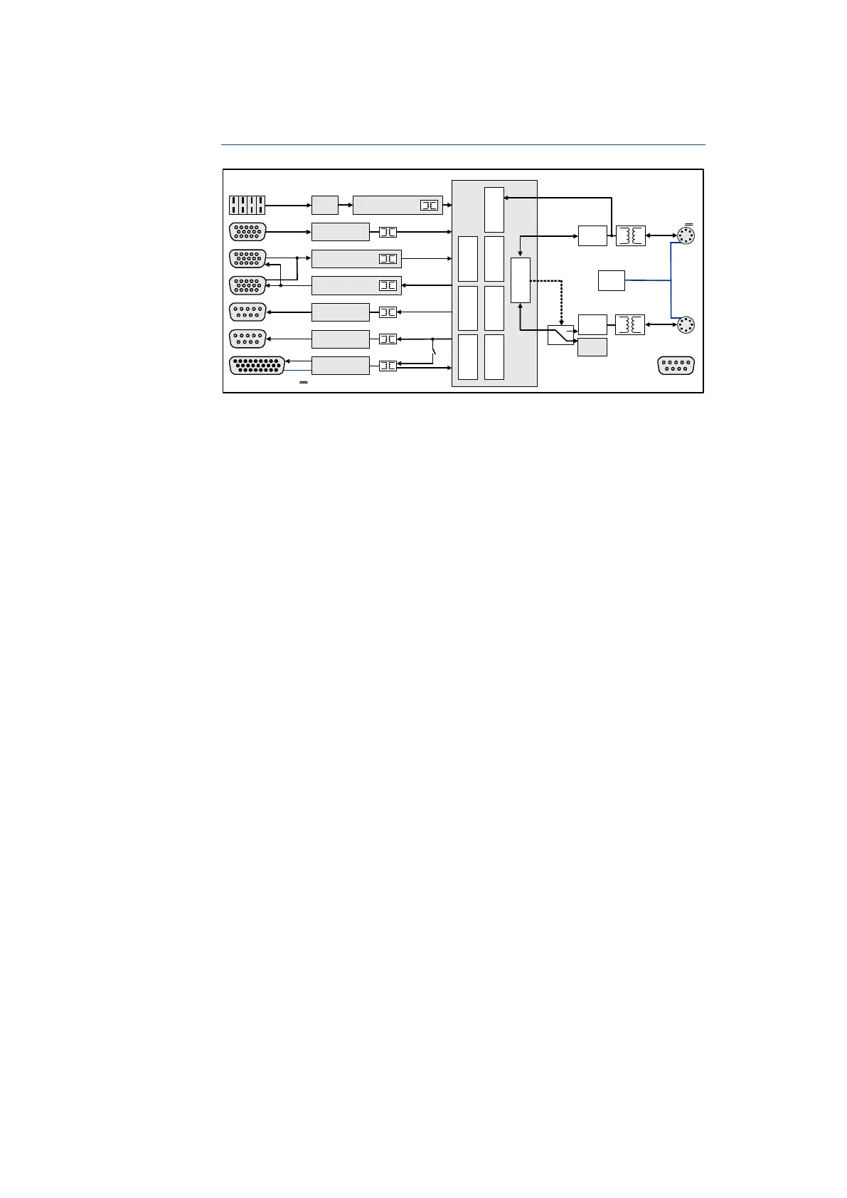
Fig. 3-4 ES930.1 Block Diagram
The block diagram in Fig. 3-4 on page 20 displays function groups of the
ES930.1 module that are described in the following chapters:
• Power supply (see chapter 3.5 on page 21)
• ETAS daisy chain connections "IN" and "OUT" (see chapter )
• Inputs and outputs
– Thermo channels "TH1" to "TH4" (see chapter 4 on page 29)
– "DI" digital input channels (see chapter 5 on page 31)
– Analog input channels "AI 1" to "AI 8" (see chapter 6 on page 45)
– Outputs to the sensor power supply (see chapter 7 on page 49)
– "AO" analog output channels (see chapter 8 on page 51)
– "DO" digital output channels (see chapter 9 on page 53)
– "PS" Half-bridges (power stages) (see chapter 10 on page 59)
The function groups of the module are described in the following chapters.
FPGA
ES930.1
Ethernet
Phy
100
MBit/s
Ethernet
Phy
Protocol Engine
Frame
Generator
Voltage
Regulator
6...32V
Output
Unit (STIM)
Diagnosis
Unit
Time
Synchronization
Unit
Meas urement
Unit (DAQ)
TH 1-4
/
4
/
4
/
4
/
6
/
6
DI
AO
DO
PS
Event UnitIn it Val ue Unit Sync Group Unit
Ext. S upply
7..32V
DC
7..29V
DC
SERVICE
Cold
Junction
/
4
Digital Input Channel n
Analog Output Channel n
Digital Output Channel n
/
4
/
6
/
4
/
6
Power Stage n with
Cur r ent Input n
Control PS n
Analog Input Channel n
Thermo Channel n
/
8
/
4
/
4
100
MBit/s
IN
Ethernet,
Power Supply
OUT
Ethernet,
Power Supply
Sensor Supply Channel n
AI5-8
/
8
AI1-4
/
4


 To Next Page