ETAS Analog Input Channels ("AI 1-4"/"AI 5-8" Connections)
ES930.1 - User Guide 46
6.2.4 A/D Converter
A 16-bit A/D converter digitizes the output signal of the analog filter. The sepa
-
rate A/D converter, which is available in every analog input channel, ensures the
synchronous sampling of the measuring signals.
6.2.5 Digital Filter
An FIR filter subsequently processes the output signal of the A/D converter.
The FIR filter is implemented as a digital FIR low-pass of the 8th order (Butter
-
worth) with adjustable limit frequency, and can be configured or disabled in the
application program.
6.2.5.1 Adjustability of the Filter
An overview of the possible settings and technical data of the digital filter is
located in chapter
13.9.5 on page 95.
6.2.5.2 Recommendations for the Configuration of the digital Filter
The -3-dB limit frequency of the digital filter system of the ES930.1 can be con-
figured in the application program.
To avoid aliasing effects, recommendations for the configuration of the filter
should be observed depending on the selected INCA sampling rate. The neces
-
sary instructions are located in the following table.
6.2.5.3 Configuration of the digital Filter for Rapid Prototyping Applica-
tions
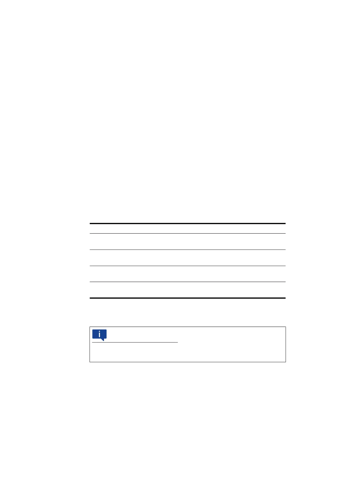
Symbol Meaning Setting
f
C,AAF
-3-dB limit frequency HW anti-
aliasing filter
10 kHz (fixed)
f
S,AD
A/D converter sampling fre-
quency
40 kHz
f
C,FIR
-3-dB limit frequency FIR filter
(adjustable)
Recommendation:
f
C,FIR
0.4 * f
S,INCA
f
S,INCA
INCA sampling frequency Configuration in the application
program
NOTE
For rapid prototyping applications, the digital filters of the analog input chan-
nels are automatically switched off.