ETAS Digital Input Channels ("DI" Connection)
ES930.1 - User Guide 31
5 Digital Input Channels ("DI" Connection)
The ES930.1 provides four digital input channels at the "DI" connection for dif-
ferent measuring functions (status, counter, timer).
5.1 Assemblies of the Digital Input Channels
5.1.1 Overview
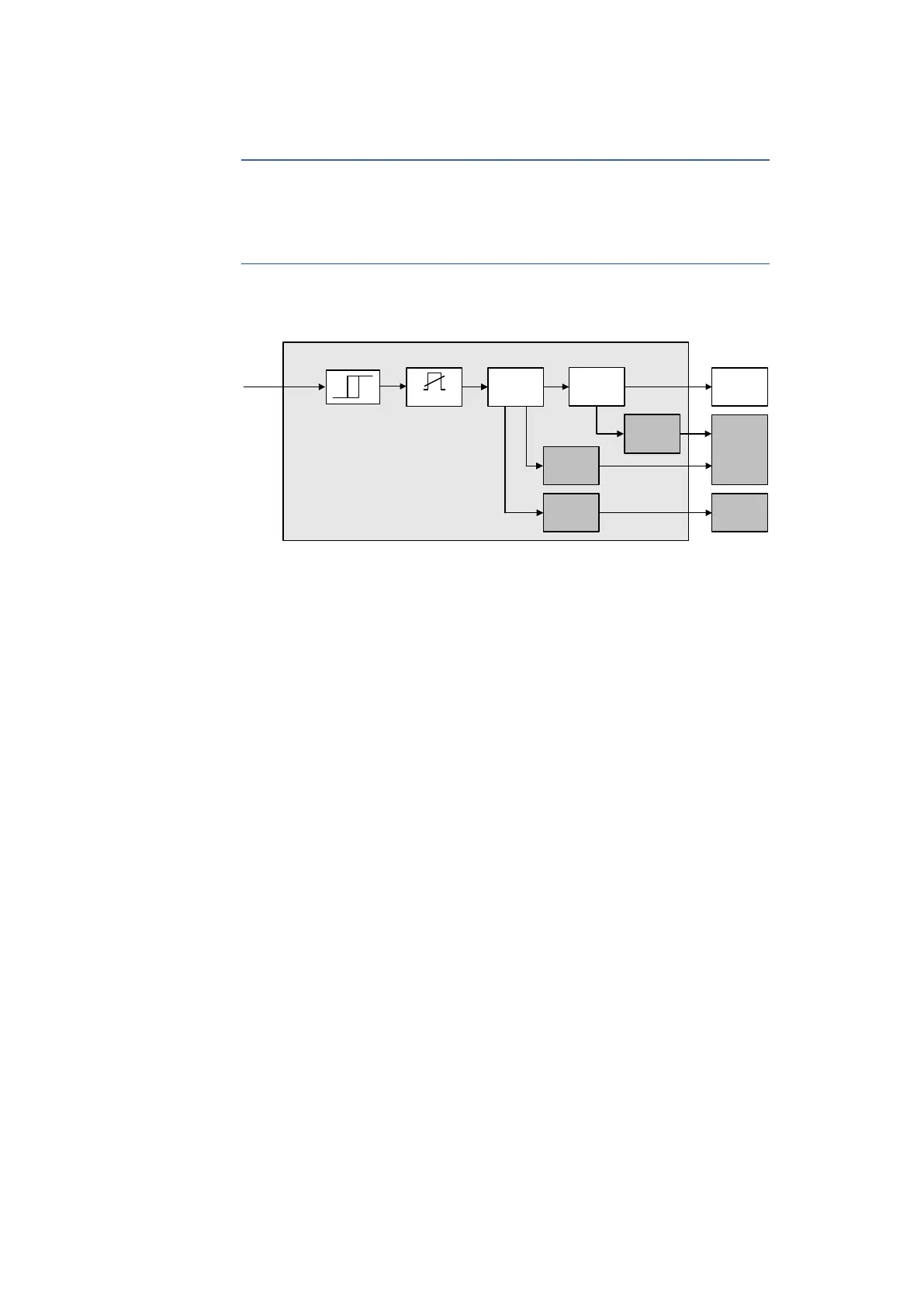
Fig. 5-1 Digital Input Channels
The digital input channels "DI 1" to "DI 4" of the ES930.1 feature an identical
design and consist of an input stage with signal acquisition and signal process
-
ing. The input stage of each channel (see in Fig. 5-1 on page 31) consists of the
following assemblies :
• Schmitt trigger (TTL-compatible)
• Glitch filter
• Capture unit
• Counter unit
• Timeout detection
• Event raster source
• Counter overflow detection
The digital input channels are dimensioned for TTL-compatible input voltages.
The minimum pulse width is restricted to 120
ns. This restriction avoids acquir-
ing interference pulses at the measuring channels.
The functionality of all digital input channels can be configured separately.
Digital Input Channel n
Diagnosis
Unit
Event Unit
Counter
Overflow
Detection
Timeout
Detection
Event Raster
Source
Counter Unit
Capture Unit
Measure-
ment
Unit
Glitch Filter


 To Next Page