ETAS Digital Input Channels ("DI" Connection)
ES930.1 - User Guide 34
5.2 Measuring Functions
5.2.1 Definitions of the measuring Signals
This section defines signals that are used for the description of the measuring
functions of the digital inputs of the ES930.1.
5.2.1.1 Legend
Tab. 5-1 on page 34 summarizes the symbols used in the figures of the chapter
on "Measuring Functions".
Tab. 5-1 Symbols used
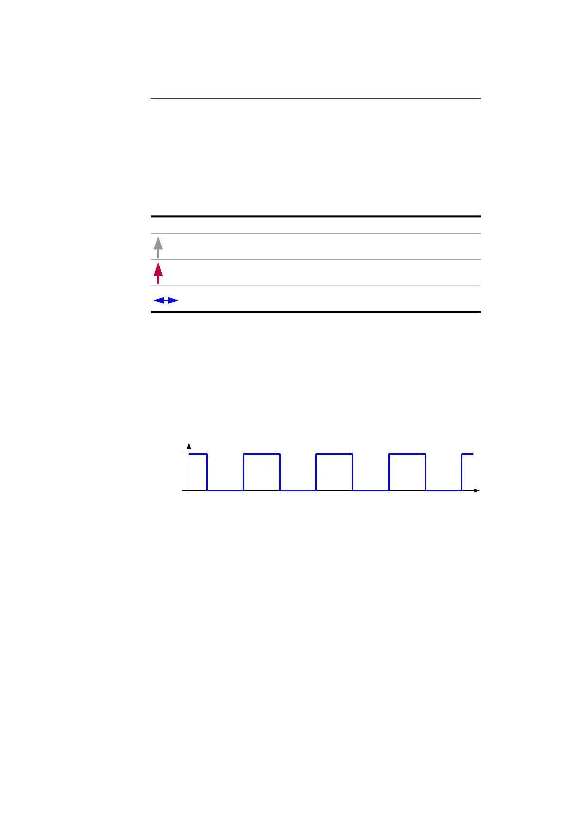
5.2.1.2 Status
The term "state" describes the level of a signal to a sampling time. The state of
an input signal is either active or inactive. The active state is represented by the
value 1 or HIGH, the inactive state by the value 0 or LOW.
Fig. 5-3 Active and inactive State
5.2.1.3 Pulse
The term "pulse" describes the time characteristic of a signal change from one
state to the other and back to the original state.
A pulse is framed exactly by one inactive-active and one active-inactive edge.
The two edges follow in succession.
The pulse of an input signal is either active or inactive. An active pulse starts
with an inactive-active edge, an inactive pulse starts with an active-inactive
edge.
Symbol Meaning
Time stamp for preceding samplings (fixed grid)
Current time stamp (fixed grid)
Resulting scan value
Time
Input
Signal
Active
Inactive
 Loading...