ETAS Digital Output Channels ("DO" Connection)
ES930.1 - User Guide 53
9 Digital Output Channels ("DO" Connection)
The ES930.1 provides six TTL-compatible digital output channels at the "DO"
connection.
Each of the digital output channels can output signals independent of each
other (Digital Out, Pulse Out and PWM Out). In addition, the channels for the
control of the Half-bridges (power output stages "PS") can be used.
The output of each channel can be released or blocked with a separate signal
("Enable DO n"). A total of two output channels can each be assigned to one of
the LEDs
U1 and U2.
9.1 Assemblies of Digital Output Channels
9.1.1 Overview
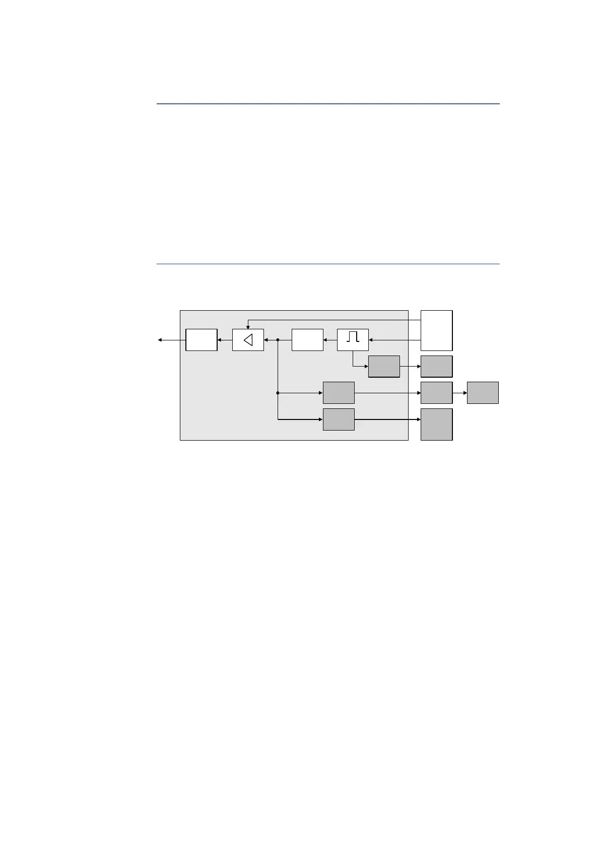
Fig. 9-1 Block Diagram of a digital Output Channel
The digital output channels "DO 1" to "DO 6" of the ES930.1 feature an identical
design. Each channel consists of the following assemblies (see block diagram
in
Fig. 9-1 on page 53):
• Counter unit
• Min pulse
• Output amplifier
• Overvoltage protection
• Min pulse adaptation detection
• LED control
• Power stage control
The functionality of all digital output channels can be configured separately.
9.1.2 Counter Unit
The counter unit generates digital output signals (Dig Out, Pulse Out, PWM Out)
with a 32-bit counter.
The counter unit is controlled by the digital output unit according to the config-
uration in the application program or the definition in the model for rapid proto-
typing applications.
Digital Output Channel n
Power Stage
Control
LED Control
Min Pulse
Adaptation
Detection
Overvoltage
Protection
DO Enable n
PS Control n
Min Pulse
Counter Unit
Diagnosis
Unit
Power Stage
LED Control
Unit
LED U1
LED U2
Output Unit