ETAS Digital Output Channels ("DO" Connection)
ES930.1 - User Guide 56
9.2 Properties
The digital output channels can provide signal frequencies in the range from
1
Hz to 60 kHz. The minimum pulse width is restricted to 150 ns. This restric-
tion prevents the generation of spikes on the output channels.
9.2.1 Output Restrictions
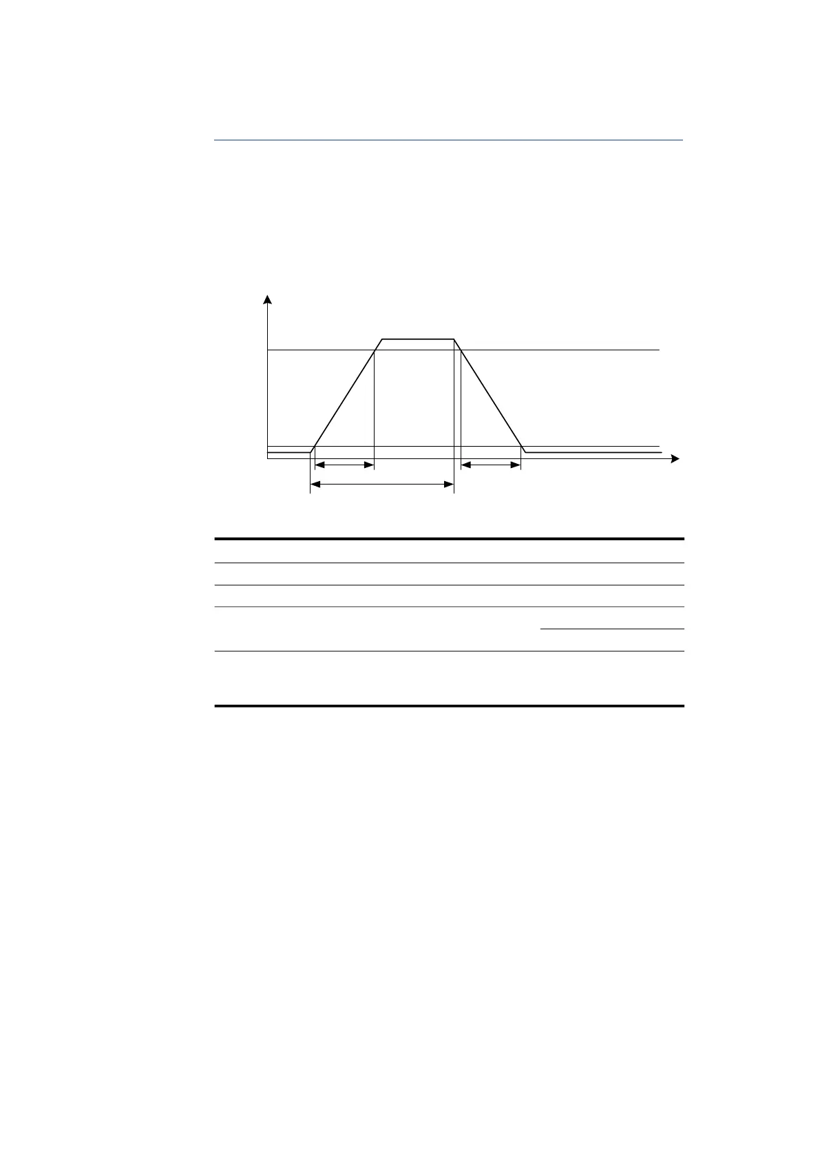
Fig. 9-2 on page 56 describes the rising and falling edge of an output signal.
Fig. 9-2 Simplified Diagram of the Output Channel Characteristics
Tab. 9-1 Digital Output Channels – Rise and Fall Time
An additional capacitive load on an output channel increases the rise and fall
times. For this reason, it is recommended that you use cables with a maximum
length of 4
m.
Symbol Description Typ.
1)
t
OUTR
Output channel rise time 200 ns
t
OUTF
Output channel fall time 200 ns
t
OUTP
Output channel pulse high time 150 ns
2.5 s
2)
1)
: measured directly at the connection of the module, 470 pF load
2)
: with control of Half-bridges
Volt age
0 V -
Ti me
1 V -
2 V -
3 V -
4 V -
t
OUTF
t
OUTP
t
OUTR
90 % of Signal Range
10 % of Signal Range