ETAS Digital Input Channels ("DI" Connection)
ES930.1 - User Guide 32
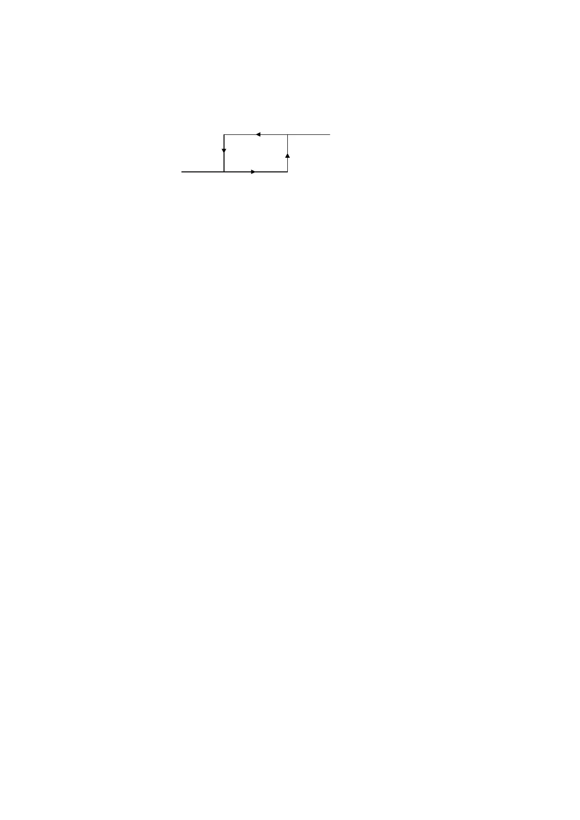
5.1.2 Schmitt Trigger
The Schmitt trigger of the input stage has a fixed hysteresis, the corresponding
switching thresholds for the LOW and HIGH levels are TTL-compatible.
Fig.
5-2 Definition of Hysteresis for the Input Channel
The hysteresis is completely defined by the two levels and the edge direction.
5.1.3 Glitch Filter
In the input stage, a glitch filter relieves the Input signal from short interference
peaks or is used, e.g. for debouncing. The filter characteristic (duration) can be
configured in the application software for the active or inactive status. The
glitch filter can be switched off, if necessary.
5.1.4 Capture Unit
In the capture unit function group, the Input signal is captured and, depending
on the selection in the application software, can be evaluated in normal or
inverted logic independent of the channel within a period or a cycle. The vari
-
ables status, active times and inactive times of the input signal are determined.
These measuring functions of the ES930.1 are described in the chapters
5.2.3
on page 37 and 5.2.5 on page 40.
5.1.5 Counter Unit
In the counter unit function group, the edges of the Input signal are counted and
processed according to the measuring function selected in the application soft
-
ware. These measuring functions of the ES930.1 are described in chapter 5.2.4
on page 38.
5.1.6 Timeout Detection
The timeout detection function group monitors the signals at the digital input
channels. It is checked whether at least one signal change occurs within a
period which can be configured separately for each measuring channel. If no
signal change occurs in the defined period, it is recognized as timeout and the
timeout flag is set for diagnostics purposes.
If the signal changes do not occur, no new timer measured values can be deter-
mined. If the timeout of the ES930.1 expired, the values measured last of the
counters, the active and the inactive time are retained without changes. They
are transferred to the application program during the next sampling.
5.1.7 Event Raster Source
In the event raster source function group, the input signal is analyzed for the
occurrence of events that were defined for this channel in the application soft
-
ware (see chapter 3.7.2 on page 26).
Log i cal 0
Log i cal 1
HIGH
Threshold
LOW
Th reshold