74 CEM3 User Manual
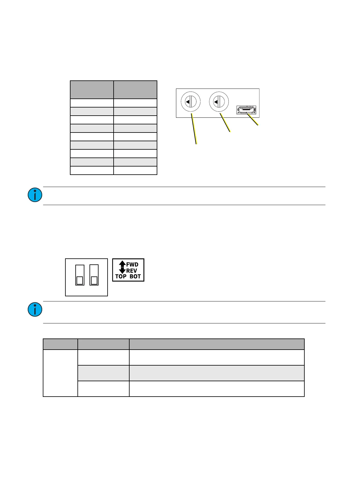
Min Scale Dials
The minimum scale for each dimmer can be set while the module is powered on. To access the min
scale dials, remove the screw securing the dial and microUSB port cover with a #1 Phillips screwdriver.
See
Phase Adept Module Top View
on
page 71
. Use a 2.4 mm flatblade screwdriver to adjust the rotary
switches. See the label on the front of the module or the table below for switch settings.
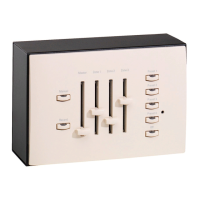
Forward/Reverse Phase Switches
To access forward or reverse phase for each circuit, remove the screw securing the cover over the
forward/reverse switch with a #1 Phillips screwdriver. See
Phase Adept Module Front View with Covers
Installed
on
page 73
. See the label on the cover or the diagram below for switch settings.
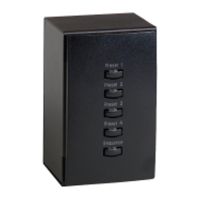
LED Error States
Note:
Both minimum scale dials are factory set to 0 (OFF) by default.
Note:
Both forward/reverse phase switches are factory set to OFF (down) by default, setting
both circuits to reverse phase.
LED Behavior Status
Fault
Steady on
Inrush current threshold exceeded or short circuit detected. See
Short Circuit Protection
on
page 69
.
Slow blink
(1 per second)
Temperature threshold exceeded.
Fast blink
(1 per half second)
Voltage threshold exceeded. See
Voltage Spike Protection
on
page
69
.
0
1
2
3
4
5
6
7
8
9
0
1
2
3
4
5
6
7
8
9
Minimum Scale Dials
MicroUSB Port
Bottom Dimmer
Minimum Scale Dial
Top Dimmer
Minimum Scale Dial
Dial Position
Minimum
Scale
0OFF
1 5%
210%
3 15%
420%
5 25%
630%
7 40%
850%
Forward/Reverse Phase Switches
ON
12
• Switches: switch 1 controls the top circuit; switch 2 controls the
bottom circuit.
• Switch position: ON (up) is forward phase; OFF (down) is
reverse phase.