31
SERVICE INFORMATION
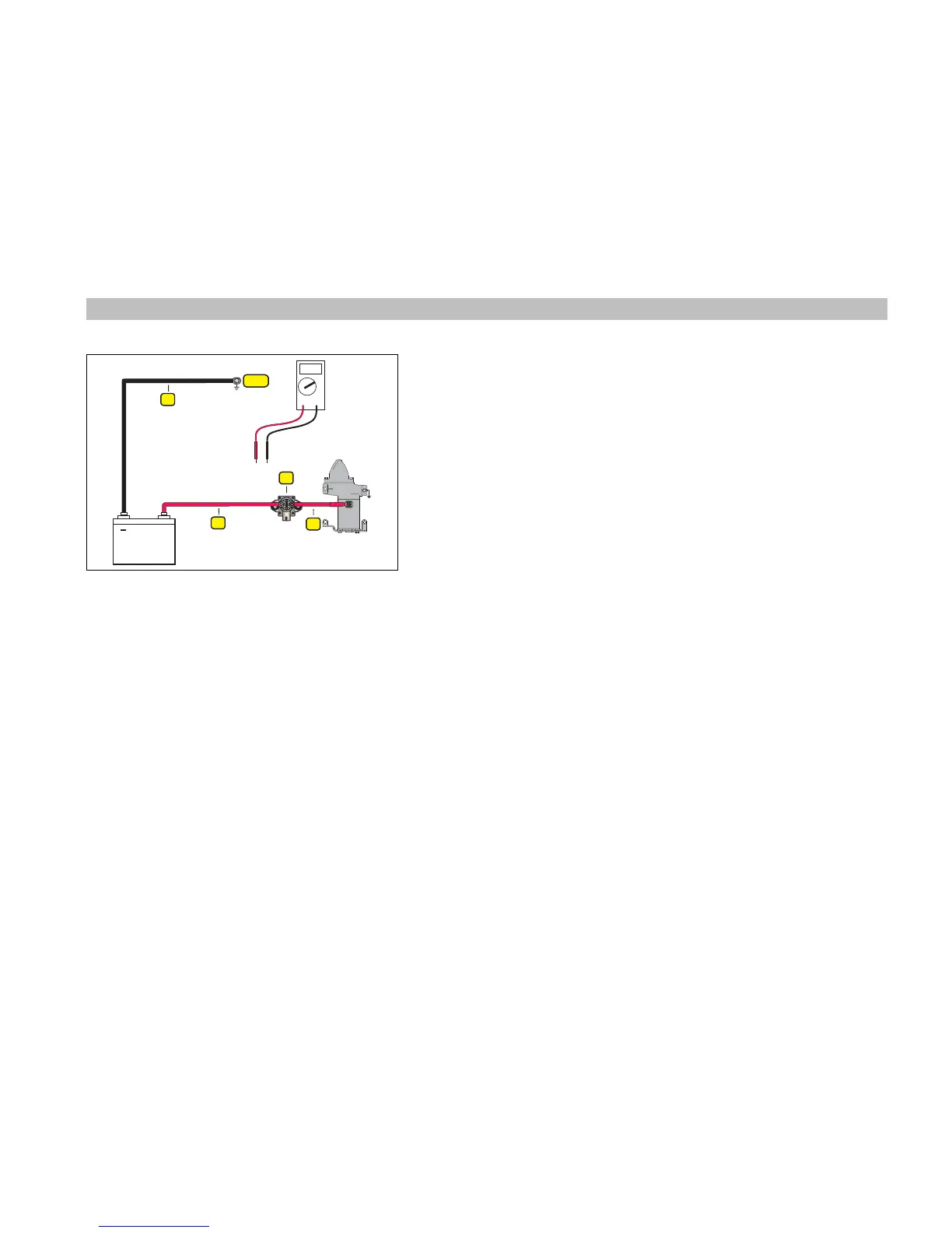
1. Negative battery cable
2. Positive battery cable
3. Solenoid
4. Starter cable
NEG
+
V –
V
1
2
3
4
Voltage Drop Test
A voltage drop test is an effective and easy to perform electrical test. The pur-
pose of this test is to make sure the load in the circuit consumes the maximum
amount of voltage. An excessive voltage drop in a circuit will result in the load
not performing at its maximum potential.
Use a digital voltmeter to measure the voltage drop on each section of the start
circuit. Always connect the voltmeter leads with the positive (+)/red lead closest
to the positive terminal and the negative (–)/black lead closest to the negative
terminal of the battery.
If any voltage reading is greater than 0.5 VDC check that connections are clean,
tight and free of corrosion. Clean or replace any corroded or damaged cables or
connections.
Note: Disconnect the Crankshaft Position Sensor (CPS) to prevent the engine
from starting.
STEP 1: Connect voltmeter positive (+) lead to the terminal for the negative (–)
battery cable at powerhead. Connect voltmeter negative (–) lead to negative (–)
battery post.
• Activate starter motor and observe voltage reading.
STEP 2: Connect positive (+) lead to battery positive (+) terminal. Connect neg-
ative (–) lead to starter solenoid terminal.
• Activate starter motor and observe voltage reading.
STEP 3: First, activate starter motor. Connect positive (+) lead to starter solenoid
terminal. Connect negative (–) lead to opposite starter solenoid terminal.
• Observe voltage reading.
STEP 4: Connect positive (+) lead to starter cable of solenoid terminal. Connect
negative (–) lead to starter motor terminal.
• Activate starter motor and observe voltage reading.