ICON INSTALLATION TIPS
Buss Cable Issues
Incorrect alignment and assembly of ICON buss cables can result in a non-func-
tional ICON network. Use the following information to avoid network communica-
tion issues.
Assemble connectors dry. Do NOT use Electrical Grease on this style connector.
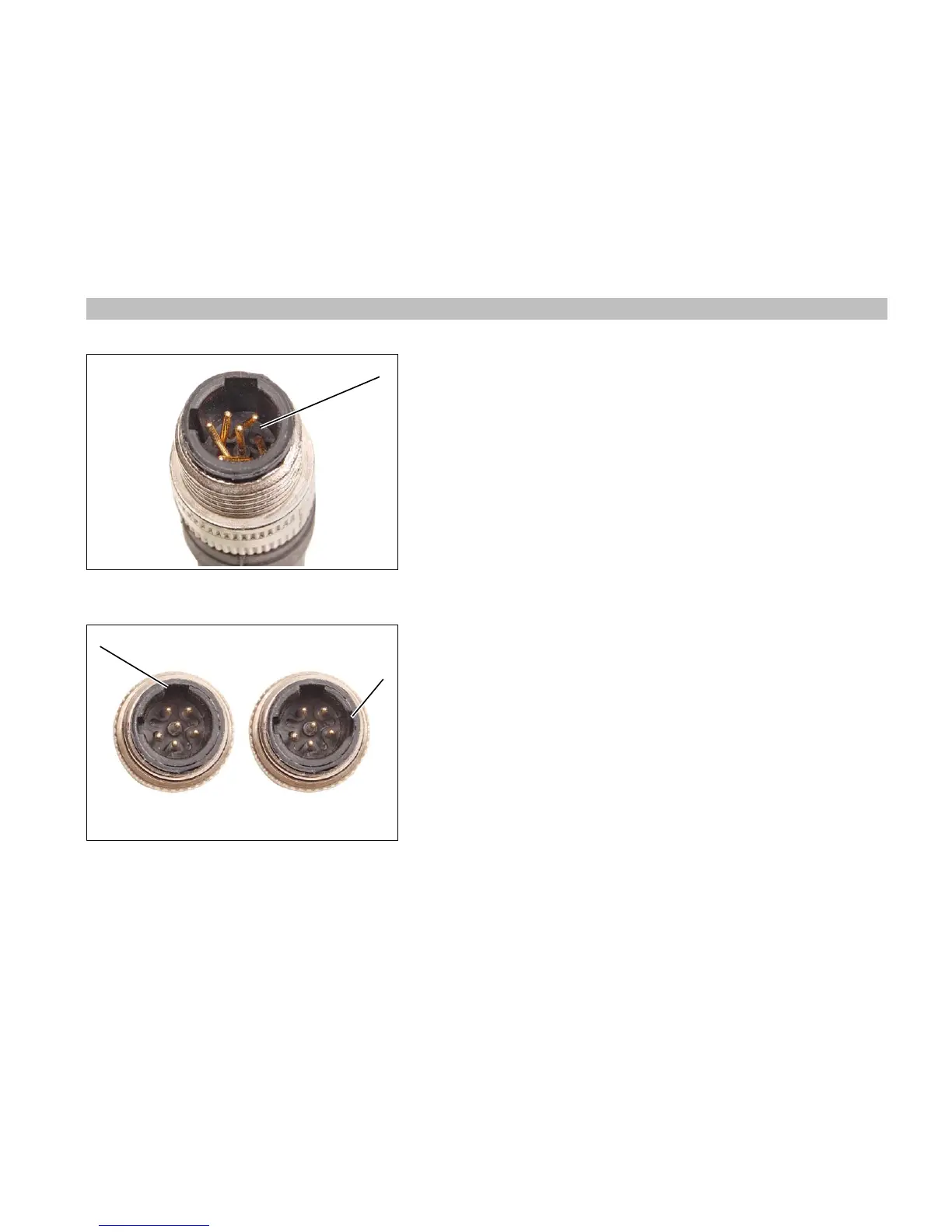
Visually check the alignment and assembly of connectors. Align tabs and sock-
ets of the female connector to the grooves and pins of the male connector.
Tighten locking rings of connectors finger-tight.
Do not rotate the connectors to align pins to sockets. This can damage the pins
of the connector. A damaged connector can cause an electrical short in the net-
work, resulting in a failed 3 Amp fuse at the master power key switch.
It is possible for the pins of one connector to enter the sockets of the other con-
nector when the tabs and grooves of the connector are misaligned. This dam-
ages the connector housing and makes an extra groove in the misaligned
connector.
Misaligned connectors can cause the 3 Amp fuse at the master power key
switch to blow and disrupt or eliminate communication on the network.
Improper network communication can create non-recoverable fault codes and
activate S.A.F.E.
 Loading...

