XT Series DISK RECORDER - Version 9.00 - Hardware Technical Reference Manual
EVS Broadcast Equipment SA – April 2008
Issue 5.00
41
3.2.1.4 CONNECTORS ON THE COD A AND COD B MODULES
Connector SD mode HD mode Connector label on rear panel
J1
SDI/CVBS (*)
monitoring output (SD)
SDI/CVBS(*) monitoring
output (SD, down-converted) Character Outs, CVBS/SDI
J2
SDI monitoring output
(SD)
SDI monitoring output
(SD, down-converted) Not connected
J3
Loop-through for the
SDI input signal (SD)
SDI program output
(SD, down-converted) SD Out
J4
SDI monitoring output
(SD)
HD SDI monitoring output
(HD) Character Outs, SD/HD
J5 Not installed Not installed n.a.
J6
SDI program output
(SD)
HD SDI program output
(HD) SD/HD Out
J7
SDI program output
(SD, identical to J6)
HD SDI program output
(HD, identical to J6) SD/HD Out
J8
SDI input
(SD)
HD SDI input
(HD) SD/HD In
J9
Alternate SDI input
(SD, for hardware
loop)
Alternate HD SDI input
(HD, for hardware loop) Used for loop in
(*) The switch between SDI and CVBS on J1 is done by a software setting in the EVS Configuration
menu.
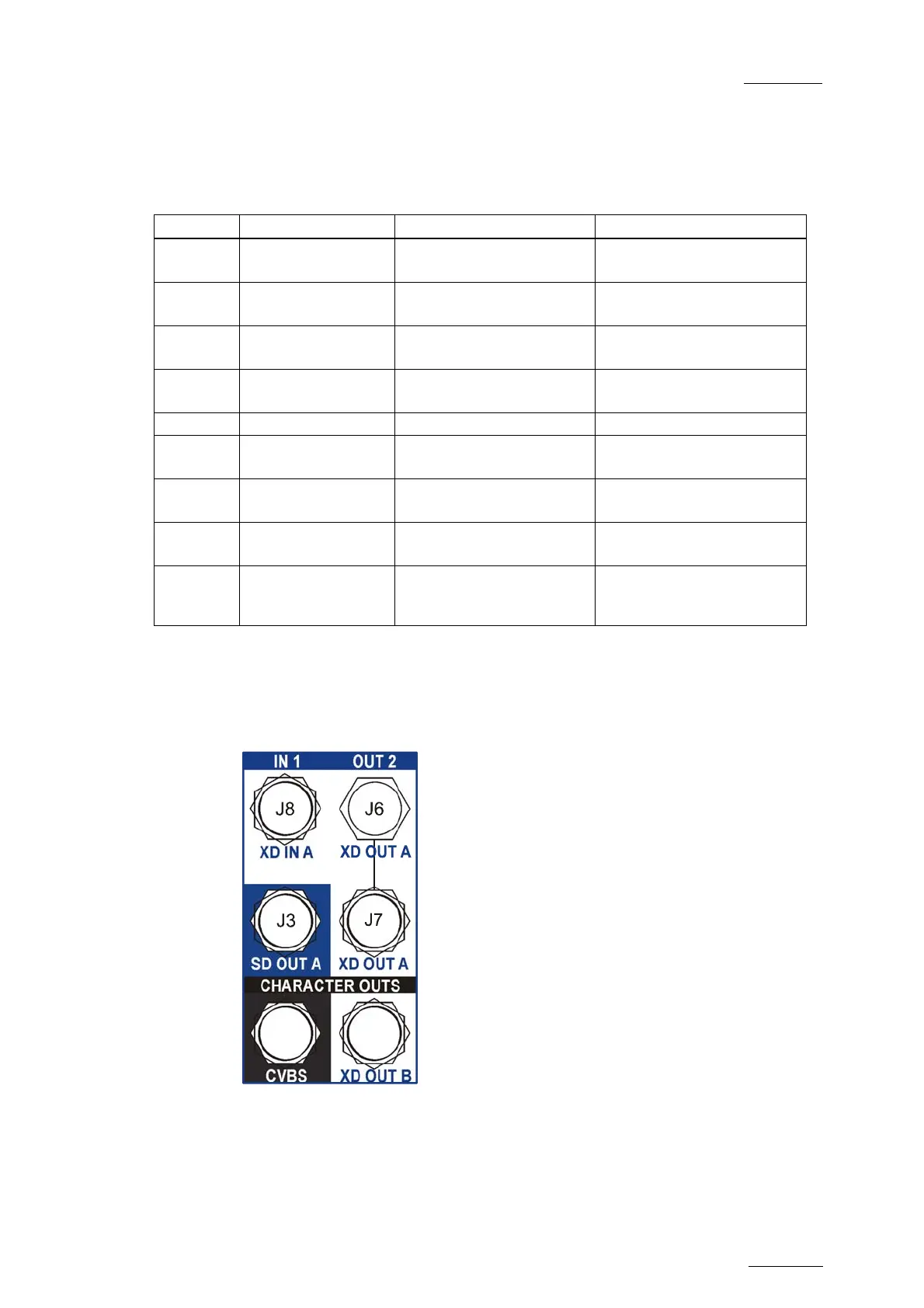
The following schema shows the connector positions:
J1 J4


![Preview: EVS XT[2]](https://data.easymanua.ls/products/617905/200x200/evs-xt-2.webp)


