8 Commissioning
8/1
8.1 Setting up the Welding Machine
Pay attention to the safety instructions “ For your safety” on the first page!
•
Set up the machine so that there is enough room to adjust the operating elements.
•
Take care that the unit is installed in a stabile position and appropriately secured to prevent it
rolling away.
8.2 Mains Connection
An appropriate mains plug must be connected to the power lead of the machine!
The connection must be carried out by a qualified electrician according to the applicable
regulations
The phase sequence is free and has no influence on the direction of rotation of the fan!
The operating voltage shown on the data plate must correspond to the mains supply
voltage!
For mains fuses please refer to the technical data (Chapter 3)!
•
Plug the switched off unit into the appropriate socket.
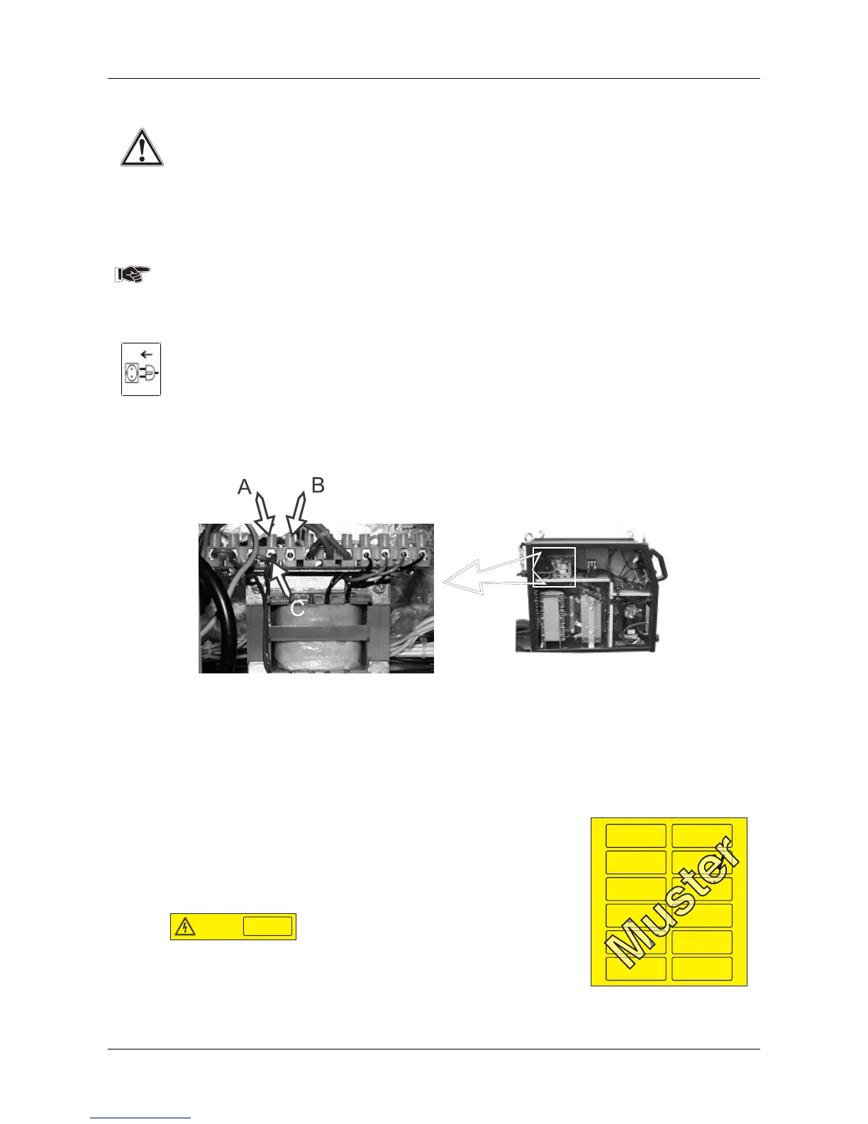
8.2.1 Reconnecting the mains voltage 400/415V at the control transformer
Fig. Control transformer
• Remove the left side panel of the welding machine (disconnect the earthing cable).
• Connect cable "C" for the required mains voltage.
- Mains voltage 415V Cable "C" must be reconnected from "A" to "B".
- Mains voltage 400V Cable "C" must be reconnected from "B" to "A".
• Connect the earthing cable to the side panel and screw tight.
Those machines that are delivered to countries with other
mains voltages than standard ones, are marked with the
following stickers:
a) Indications of mains voltage: see at the end of the mains cable
b) Mains voltage connected ex works: see at the back
side of the machine, above the data plate!
Netzanschluß-
spannung
Mains voltage
400V
c) Sticker with special mains voltages, needed for
the marking by yourselves are enclosed with the
operation manual.
After reclamping to 415 V, the
• sticker c) has to be sticked upon sticker b) and
• sticker a) has to be removed from the end of the cable.
230V 230V
400V 400V
415V 415V
460V 460V
500V 500V
___V ___V