4 Description of the System components
4/3
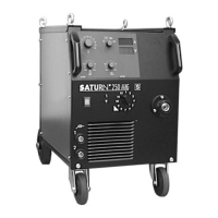
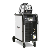
4.2.1 SATURN 200 - 300 Welding Machine Series (Front- and rearview)
A1 Transport handle
B1 Control "PROGRAM" M201 / M100
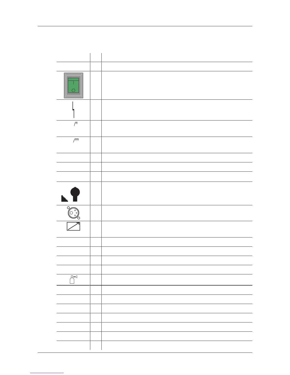
C1 Main Switch, Machine On/Off
D1 LED for fault display for excess temperature and / or lack of coolant
1
E1 Welding Current Bush -, Work-piece connection
Choke tapping CO
2
(hard)
2
F1 Welding Current Bush -, Work-piece connection
Choke tapping MIX (medium)
G1 Rollers
H1 Crane lifting lugs
Option
I1 Welding current and voltage display M110
1
12
11
10
9
86
5
4
3
2
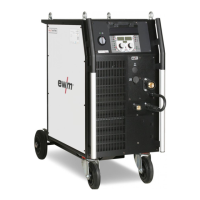
J1 Step Switch, Fine setting for welding voltage (M100) or power (M201)
(MIG 200/250: 12 Steps), (MIG 300: 15 Steps)
K1 Welding Torch Connection +, (Euro-central connection)
L1
Remote Control Socket (Option), 19 pole connection for remote control or
control cable from the welding torch
M1 Air inlet opening
N1 Turning Roller
O1 Safety chain for gas cylinder
P1 Support for shielding gas cylinders
A2 Gas Connection G 1/4"
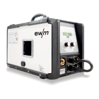
A1 Fuse, Control (42V / 4A slow-acting)
B1 Mains cable
C1 Opening for air outlet
D1 Adjustment setting - Gas after-flow
E1 Adjustment setting - wire burn-back
F1 Button for arc off wire threading
G1 polarity switching for cored wire welding (Option)