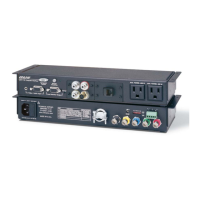
SSP 200 • Panel Features 9
Individual output settings are configured through PCS (see Speaker Placement) or
SIS commands (Layouts and Speakers on page78). Refer to the following table for
output designations.
Numbers Abbreviations Channel Description
1 LF Left Front
2 RF Right Front
3 C Center
4 SUB Subwoofer (Mono)
5 LS Left Surround
6 RS Right Surround
7 see note below
8 see note below
9 see note below
10 see note below
NOTES:
• Numbers 7 through 10 are configurable as Back, Height, or Downmix using PCS.
• The default configuration is 7.1 with Downmix on numbers 9 and 10
enabled.
For information about speaker configuration and output formats, see Listening Mode
Options and Usage on page27. See figure9 for audio output connector wiring.
3-pole Audio Output Wiring
Unbalanced Output
Tip
Sleeve
NO Ground Here
Balanced Output
Tip
e
Ring
Tip
Sleeve
Tip
Sleeve
Tip
ve
Ring
Tip
ve
Ring
6-pole Audio Output Wiring
Balanced Output Unbalanced Outpu
NO Ground Here
NO Ground Here
Figure 9. Audio Output Wiring
ATTENTION:
• For unbalanced audio, connect the sleeves to the ground contact. DO NOT
connect the sleeves to the negative (–) contacts.
• Pour l’audio asymétrique, connectez les manchons au contact au sol. Ne PAS
connecter les manchons aux contacts négatifs (–).
9