TLP Pro x25 Series and TLS x25 Series • Panel Features 14
C
Cable guide (see figure 5 on page 13) — The Ethernet cable is inserted through this hole at the back of the
base (see LAN/PoE connector on page 14).
D
RESET LED — Provides feedback about the reset status when the user presses the RESET button (see Reset
Modes on page 38).
E
LAN/PoE connector — These touchpanels must be powered by Power over Ethernet (PoE; see “Connecting
Power”, below).
ATTENTION:
• Do not power on the touchpanels or control processors until you have read the ATTENTION about
Power over Ethernet (PoE) power supplies (see page 15).
• Ne branchez pas les écrans tactiles ou les processeurs de contrôle avant d’avoir lu la mise en
garde sur les sources d’alimentation via Ethernet (PoE) (voir page 15).
NOTE: The touchpanels ship without a power injector. The power injector must be purchased separately.
An Extron IPL Pro control processor must also be connected to the same network domain as the TouchLink
Pro touchpanel (see the www.extron.com for a list of suggested models).
The network port has two LEDs. The green LED lights steadily to indicate that the touchpanel is connected
correctly to a network. The yellow LED blinks to indicate that data is being passed to or from the touchpanel.
F
Speaker — A single speaker provides audible feedback for the user.
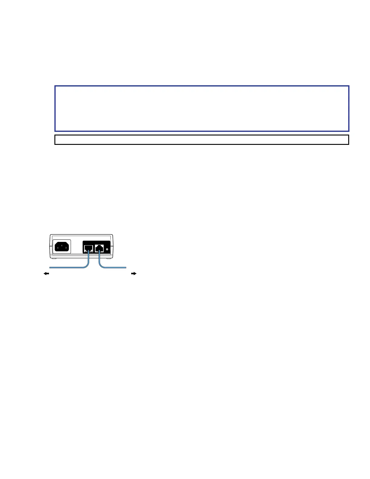
Connecting Power
These touchpanels must be powered by Power over Ethernet (PoE). Users must provide their own PoE power
injector. Figure 6 shows the Extron XTP PI 100. Your power injector may look different.
100-240V
~
50-60Hz
0.4A MAX
XTP
PWR
XTP PWR
To network switchTo touchpanel
1
2
3
3
Figure 6. XTP PI 100 Power Injector
1. Connect a straight-through Ethernet cable from the power injector to a switch or router (figure 6,
1
). This
cable carries network information from the switch or router to the power supply.
2. Connect a second straight-through cable (
2
) from the power injector to the touchpanel. This cable carries
the network information and 48 VDC from the power injector to the touchpanel.
3. Connect the IEC power cord to a convenient 100 VAC to 240 VAC, 50-60 Hz power source (
3
).
Alternatively, connect the touchpanel to a PoE switch.
Cable guide
RESET LED
LAN/PoE connector
Speaker