TLP Pro x25 Series and TLS x25 Series • Reference Material 37
Digital I/O Port Cases
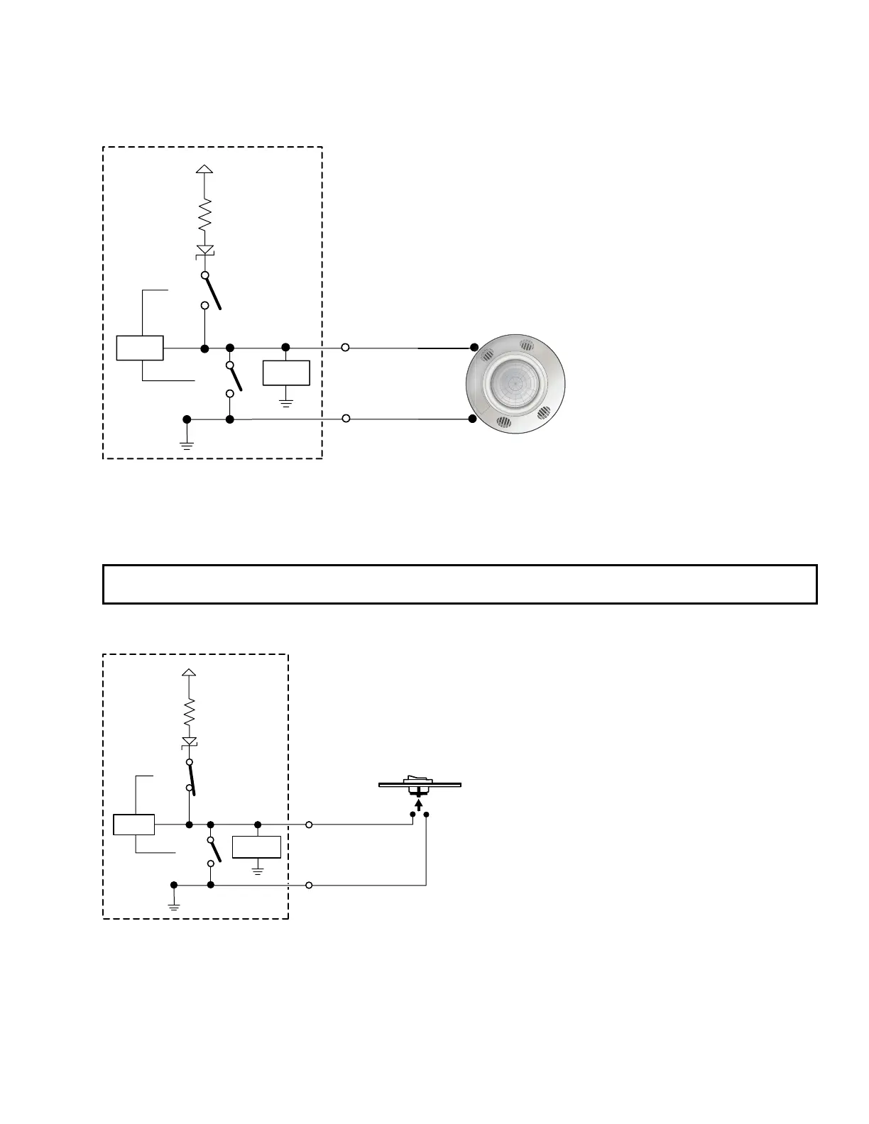
Connecting an Occupancy Sensor to the Digital I/O Port
+5.0 V
1k ohms
SW 2
SW 1
Digital
I/O
Control
Signal
Ground
GND
Voltage
Protection
CTL
Figure 30. Connecting an Occupancy Sensor to the Digital I/O Port
Port Configured — Input (switch 1 open, switch 2 open)
Room Occupied — Digital input reads +2.8 to 24 VDC = Logic High
Room Unoccupied — Digital Input reads 0 VDC = Logic Low
NOTE: An occupancy sensor typically supplies +24 VDC when occupancy is detected. After a defined period
when no occupancy is detected, the sensor supplies 0 VDC.
Connecting a Two-position Switch to the Digital I/O Port
+5.0 V
1k ohms
SW 2
SW 1
Two-position
Switch
Digital
I/O
GND
Voltage
Protection
CTL
Figure 31. Connecting a Two-position Switch to the Digital I/O Port
Port Configured — Input with pullup (switch 1 open, switch 2 closed)
Two Position Switch Open — Digital input reads +5 VDC = Logic High
Two Position Switch Closed — Digital Input reads 0 VDC = Logic Low