TLP Pro x25 Series and TLS x25 Series • Panel Features 13
K
Rear status light — The TLS 525M and TLP Pro 525M do not have any rear panel status lights. The
TLS 725M and TLP Pro 725M has six LEDs (three on each side of the rear panel). The TLS 1025M and
TLP Pro 1025M have a single LED strip on each side. The TLP Pro 525T, TLP Pro 725T, and TLP Pro 1025T
have a single LED (top center of the rear panel).
The lights can blink or remain steadily lit and they can light red or green. The lights can be configured (using
Global Configurator) or programmed (using ControlScript Deployment Utility) to provide feedback information
about the system using these variables. Different combinations, for example a red LED lit steadily or a green
LED that is blinking, can provide indications about the system. For information about setting up these LEDs,
see the Global Configurator Help File or the ControlScript Deployment Utility Help File.
The rear panel status lights of the TLP Pro 725M and the TLP Pro 1025M can be disabled, using the On-
screen Menus (see page 16).
L
Cable guide (TLP Pro 525T, 725T, and 1025T only) — The Ethernet cable is inserted through this hole at the
back of the base (also see figure 5,
C
, below).
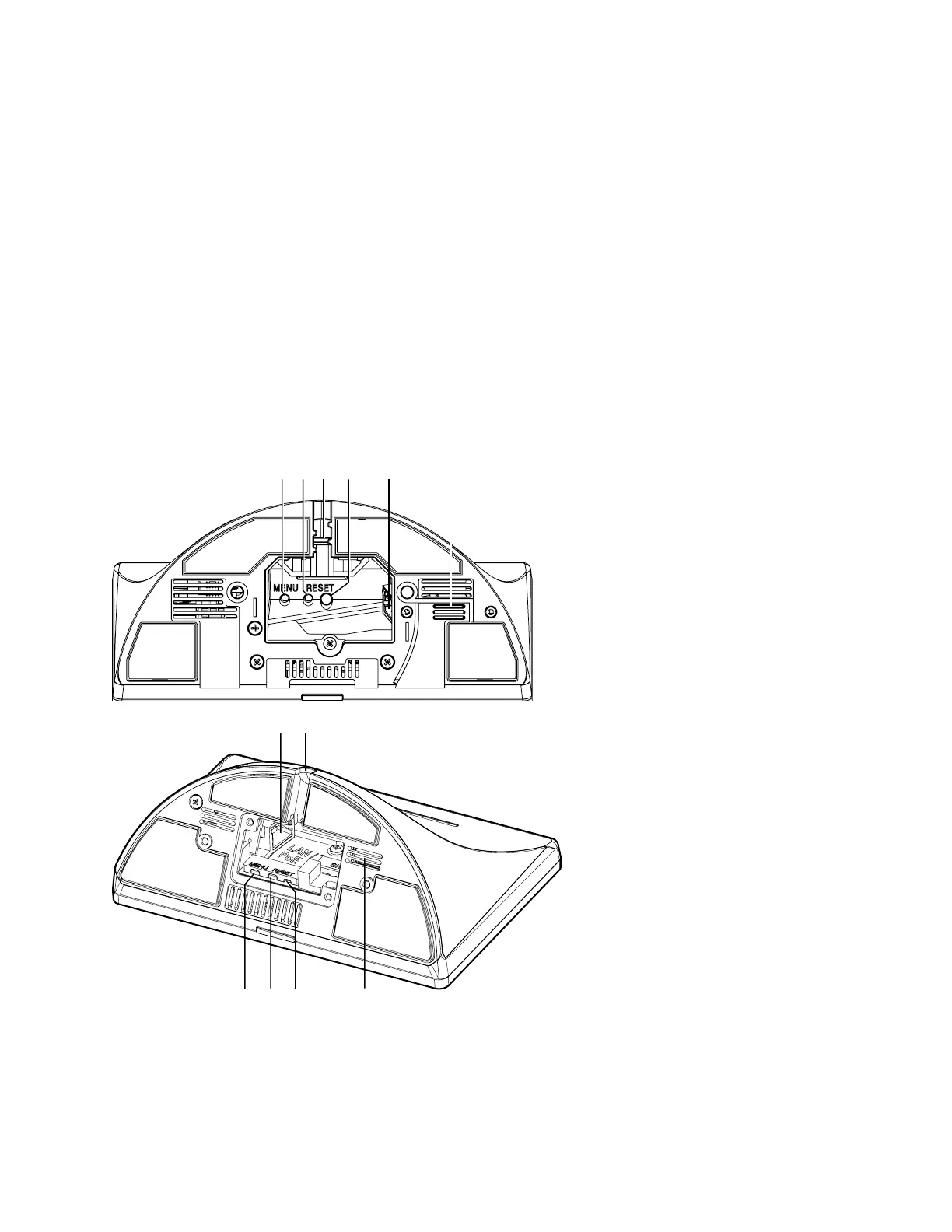
TLP Pro 525T, TLP Pro 725T, and TLP Pro 1025T Base
Figure 5 shows the TLP Pro 725T (top) and the TLP Pro 525T base (bottom). TLP Pro 1025T base is similar to
the TLP Pro 725T base.
A
AB
BC
CD
DE
EF
F
E
EC
C
A
AB
BD
DF
F
Figure 5. TLP Pro 725T (top) and TLP Pro 525T (bottom) Base
A
MENU button — Activates the On-screen Menus (see page 16).
B
RESET button — Pressing the RESET button allows the unit to be reset in any of three different modes and
can also be used to toggle between enabling and disabling the DHCP client (see Reset Modes on page 38).
Rear status light
Cable guide
gure 5
A
MENU button
B
RESET button
C
Cable guide
D
RESET LED
E
LAN/PoE connector
F
Speaker