TLP Pro x25 Series and TLS x25 Series • Mounting 33
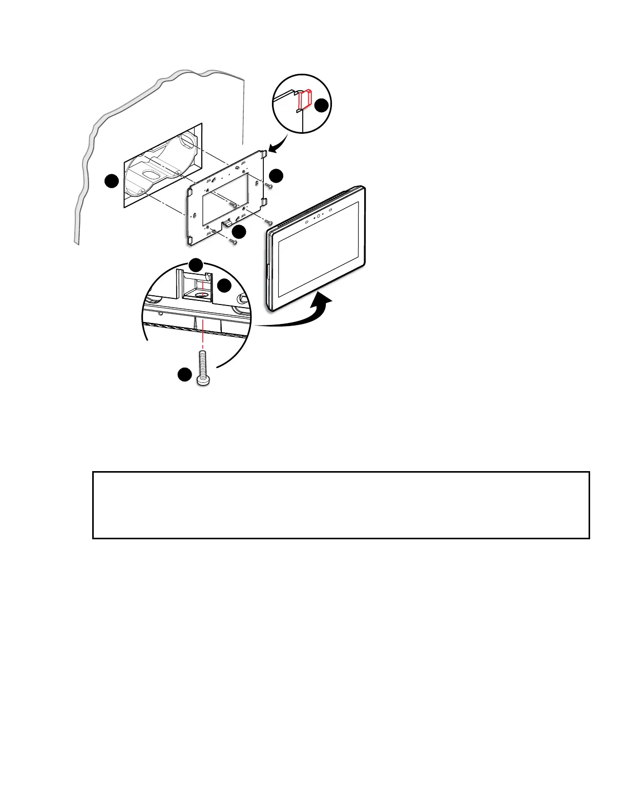
Figure 28 shows how to mount the TLP Pro 725M. Mounting the all the other touchpanels is very similar.
TOP
e
Back View
1
2
3
4
5
6
4
Figure 28. Mounting the TLP Pro 725M to a Wall Box (left) and Mounting Plate (right)
1. Install a junction box or wall box (see figure 28,
1
), following the instructions provided by the manufacturer.
2. Make sure you have the correct mounting plate for your touchpanel and fasten it to the wall with the provided
screws (
2
). Use the mounting holes that are appropriate to the junction box you are using (see figure 27 on
page 32).
NOTES:
• Extron provides four 3/4” #6-32 Philips pan head screws for mounting to US junction boxes.
• Extron provides two 16 mm M 3.5 Philips pan head screws for mounting to MK junction boxes.
• EU junction boxes are usually provided with their own screws.
3. Run and connect cables to the back of the touchpanel (see Rear Panel Features on page 11).
4. Position the touch panel so that the mounting slots in the rear of the touchpanel align with the hooks on the
mounting plate. The TLP Pro 725M and 1025M mounting plate has four hooks (
3
), one in each corner, top
and bottom. The TLP Pro 525M mounting plate has two hooks, one in each corner at the top.
5. Move the touchpanel inwards so that slots move over the hooks.
6. Move the touchpanel down so that touchpanel is seated securely on the hooks and the tongue at the bottom
of the mounting plate (
4
) is sitting in a groove in the bottom of the touchpanel (see inset,
5
).
7. Tighten the mounting screw (
6
) to fasten the touchpanel to the mounting plate.
steps 3 through 7
gure 28