Reset Button and LED
E
Reset button —
NOTE: See figure 2 on page 11, figure 3 on page 12, and figure 5 on page 14.
The Reset button initiates four levels of matrix switcher reset. For resets, press
and hold the button while the switcher is running or while you power up the
switcher (see Rear Panel Operations on page 65 for details).
Power
F
AC power connector (XTP II CrossPoint 1600 and XTP II CrossPoint 3200)—
NOTE: See figure 2 on page 11 and figure 3 on page 12.
Plug a standard IEC power cord into this connector to connect the switcher to a
100 VAC to 240 VAC, 50-60 Hz power source.
G
Attached AC power connector (XTP II CrossPoint 6400) —
NOTE: See figure 5 on page 14.
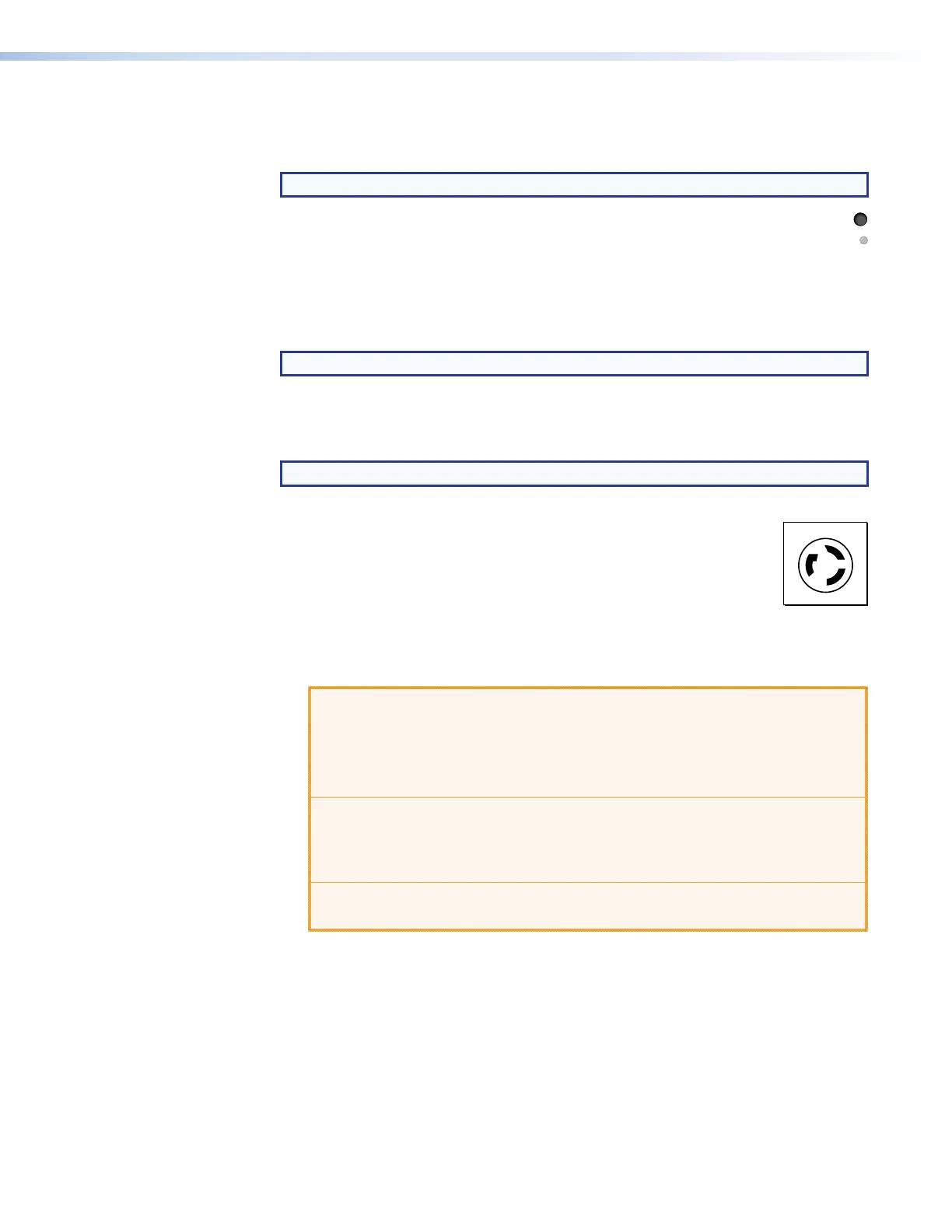
• North America — Plug the power cord into a NEMA L6-20
North America
Hot Y: Hot
G
X
Y
220 VAC, 60 Hz power outlet (see the drawing at right).
• Other regions — Have a licensed electrician install a 200-240
VAC power connector, standard for the switcher installation site
and plug the power cord into a 200-240 VAC, 50-60 Hz power
outlet (see Replacing and Terminating the Power Cable
(XTP II CrossPoint 6400) on page 147). Ensure that the wiring is
in accordance with the electrical code for the country or region where
installed and the wiring color code in force for the installation site.
ATTENTION:
• The outlet or junction box must be installed near the equipment and be
easily accessible.
• La prise de courant ou la boîte de jonction doivent être installées près du
dispositif et être facilement accessibles
• The installation location must provide short circuit and overcurrent
protection, to a minimum of 20 A.
• Le lieu d’installation doit disposer d’une protection contre les courts-
circuits et la surtension de 20 A minimum.
• Do NOT use an extension cord.
• Ne PAS utiliser de rallonge électrique.
XTP II CrossPoint 1600, 3200, and 6400 Switchers • Installation 28