Front Panel Configuration Port and Power LEDs
CONTROL
ENTER PRESET
VIEW
ESC
XTP II CrossPoint 3200XTP II CrossPoint 6400
AUDIO
VIDEO
I/O
CONTROL
ENTER PRESET
VIEW
ESC
AUDIO
VIDEO
I/O
XTP SERIES DIGITAL MATRIX SWITCHER
CONFIG
XTP SERIES DIGITAL MATRIX SWITCHER
1
2
3
4
POWER
CONFIG
PRIMARY
REDUNDANT
POWER
12
AUDIO
1
2
3
4
VIDEO
I/O
POWER
CONTROL
ENTER PRESET
VIEW
ESC
CONFIG
XTP II CROSSPOINT 1600
XTP II CROSSPOINT 3200
AABBAAAA BBBB
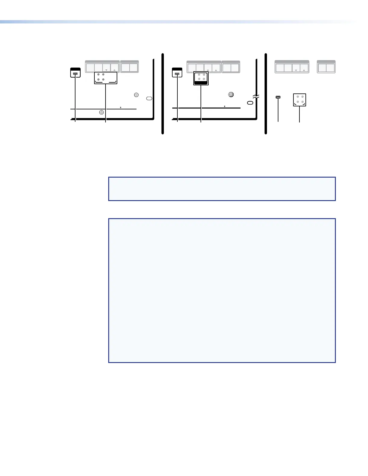
Figure 29. Front Panel Configuration (Config) Port and Power LEDs
A
Configuration port — This USB mini-B port serves a similar communications function
as the rear panel Remote port, but it is easier to access than the rear port after the
matrix switcher has been installed and cabled.
NOTE: A front panel Configuration port connection and a rear panel Remote port
connection can both be active at the same time. If commands are sent to both
simultaneously, the command that reaches the processor first is handled first.
B
Power LEDs —
NOTES:
• The XTP II CrossPoint 6400 and XTP II CrossPoint 3200 have four power
supplies installed. These power supplies are indicated by the following LEDs:
• LEDs 1 and 2 — Indicate the status of the two primary 12 V supplies.
• LED 3 — Indicates the status of the redundant 12 V supply.
• LED 4 — Indicates the status of the 48 V power supply, which provides PoX.
• The XTP II CrossPoint 1600 has two power supplies, which provide 12 V and
48 V in its standard configuration, with two optional, redundant second power
supplies available. These power supplies are indicated by the following LEDs:
• Primary LED 1 — Indicates the status from the standard primary 12 V
supply.
• Redundant LED 1 — Indicates the status of 12 V from the optional
redundant supply.
• Primary LED 2 — Indicates the status from the standard primary 48 V
supply, which provides PoX.
• Redundant LED 2 — Indicates the status of 48 V from the optional
redundant supply.
Green — Indicates that the associated power supply is operating within normal
tolerances.
Red — Indicates that the associated power supply is operating outside the normal
tolerances or has failed.
XTP II CrossPoint 1600, 3200, and 6400 Switchers • Installation 29