28
0
1
2
3
4
5
min - max
7 -12 bar
6 bar
"
!
!
#
"
$
%
!
Dust Extractor
RL 250 / RL 300 / RL 350
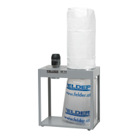
The RL 250-350 has to be connected to a supply of
compressed air whilst it is in operation.
Connect the customer-side feed line according to the
data on the servicing unit (see pneumatic plan).
The pressure in the feed line must measure at least 7 bar
(max. 12 bar). The pressure reducer adjustment has to
be executed so that the manometer displays 6 bar.
Depending on the length of operating time, the conden-
sation receptable has to be emptied on a regular basis.
See chapter entitled: >Service<
!Compressed air supply connection
" Condensation receptacle
Attention! Compressed air must be free of oil, condensate and particles according to: ISO 8573-1 5-4-3
Inner diameter min. 19 mm (3/4 inch) | Max. limit pressure: 7 bar
> 7 bar: The pneumatic system is being vented.
!Compressed air supply connection
" Condensation receptacle
6.6 Connect the compressed air supply
Fig. 6-9: Connect the compressed air supply
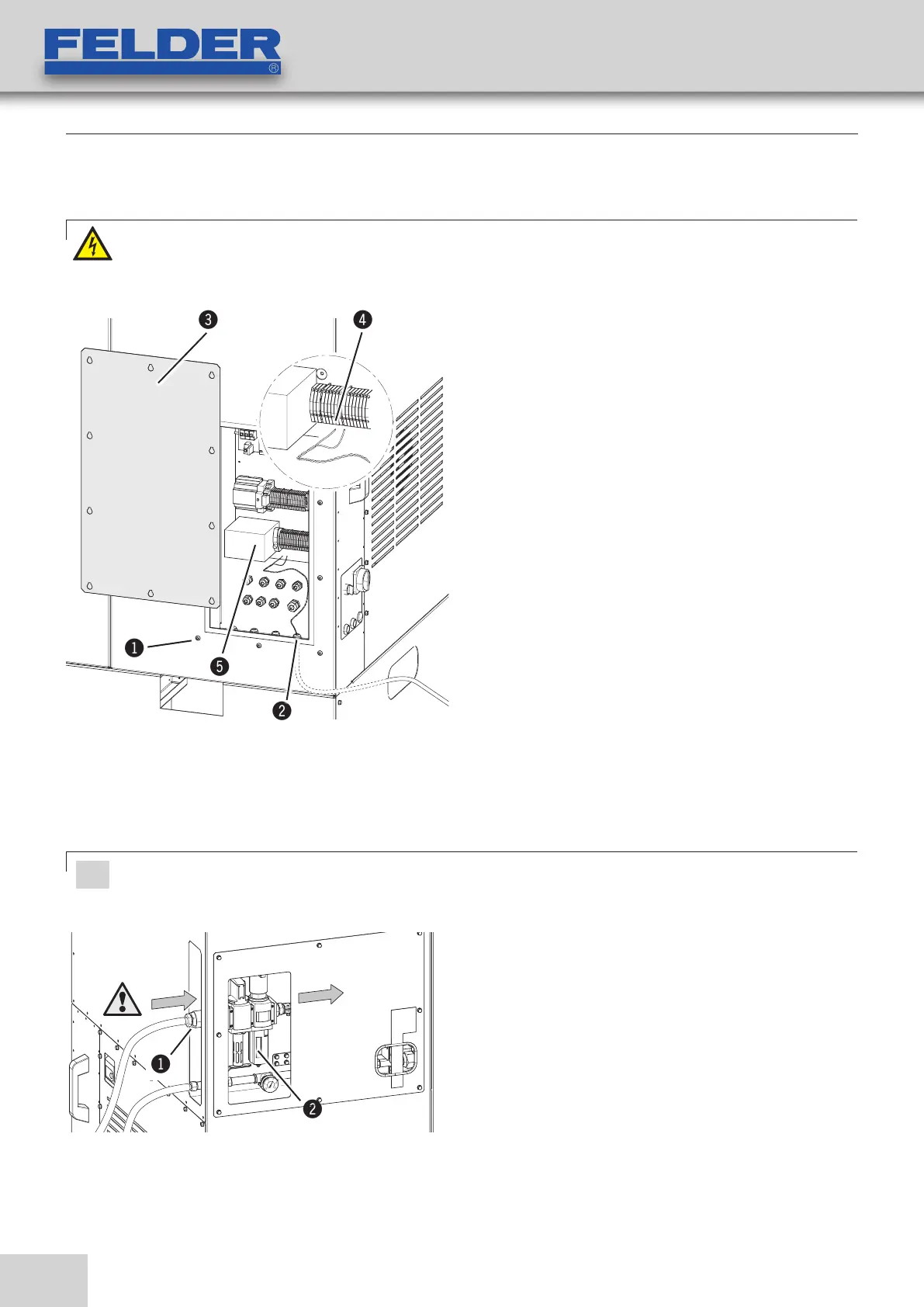
!Screws
"Cable guide
#Cover plate
Terminal block (see circuit plan):
$Woodworking machinery
%Gate valve (Option)
Fig. 6-8.2: Electrical connection - Automatik
Woodworking machinery / Gate valve
Electrical connection - see circuit plan
1. Loosen the screw and take off the covering lid.
(10 x Screws)
2. Thread the power supply cord through the cable pro-
file in the switch box.
3. Connect the wooworking machine's power supply
cord to the terminals (see circuit plan).
4. Connect the gate valve's power supply cord to the
terminals. (Option)
5. Mount the cover plate on again.
Warning! Danger! Electric current!
Work on electrical fittings may only be carried out by qualified personnel and in strict observance of the
safety instructions.
Setup and installation
6.5.2 Automatic Starting Device