6.4 Adjustments
6.4.1 Microswitches
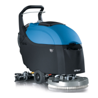
Check functionality and conditions of
the brush motor microswitch, the vac-
uum motor microswitch and the curve
speed reduction microswitch. Check
that with microswitch pressed, remain
about 0.5 mm clearance between the
lever and the body of the device. Make
sure the lever of the micro is working
properly. Otherwise, proceed as follows:
• Loosen the fixing screws.
• Move the microswitches using the
loop adjustment.
• Tighten the screws to lock the mi-
croswitches taking care not to over
tighten in order not to ruin the de-
vices.
• When the setting is finished, verify
the correct functionality of the mi-
croswitches.
6.4.1-94 6.4.1-95
6.4.1-96 6.4.1-97
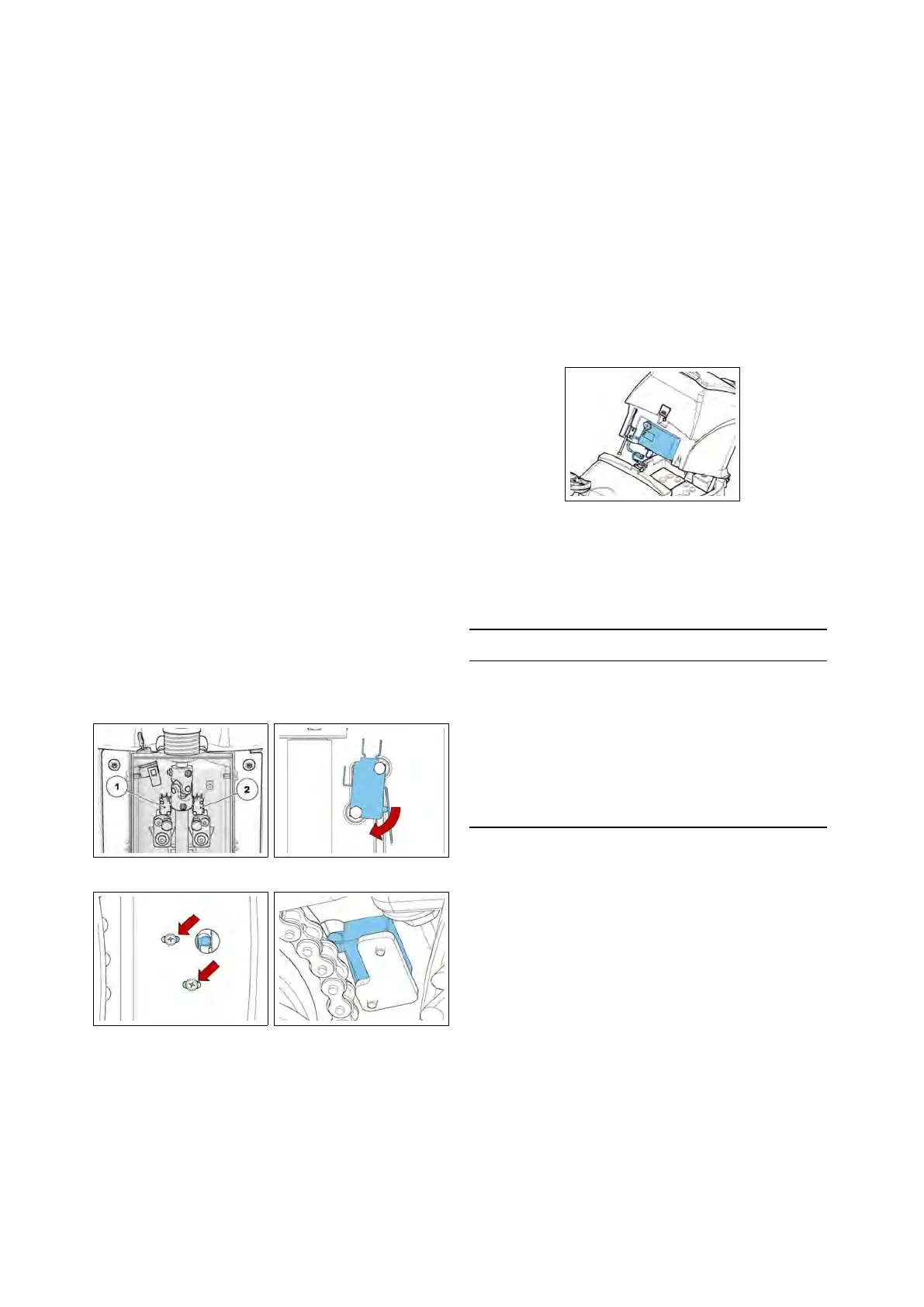
6.4.2 Battery Charger (CB)
The battery charger is positioned behind
the operator’s seat and is easily accessi-
ble by pressing the release button on the
recovery tank.
At the start of the charging cycle the
GREEN LED blinks to indicate which
charging algorithm is selected. Subse-
quently the RED LED blinks to indicate
the battery status check.
6.4.2-98
A Proper Charging cycle follows the be-
low phases order.
Phase LED Description
A Green Blinking, confirms the
recharge Setting
B Red Blinking, check of battery
status
C Red First charging phase
D YellowSecond charging phase
E Green Charged battery
Check if the charger is properly set ac-
cording to the installed batteries.
Charging curve SetUp
To set up the charger, follow the instruc-
tions:
• Use a screwdriver to remove the
small black plastic cap
• Set-up the internal dipswitches ac-
cording to the following table
The dipswitches are divided in two cou-
ples. The upper couple are the dip-
switches 1 and 2, the lower couple are
46