5.1.8 Curve Speed Reduction
Switch
• Put the machine in safe conditions.
• Remove the screws to remove the
footrest.
• Disconnect the wires connected to
the switch.
• Unscrew the two screws holding the
switch to the frame and remove it to-
gether with the protective plate.
5.2 Mechanical Friction
System
5.2.1 Brush Deck Assembly
• Release the brush from the Brush
Deck.
• Put the machine in safe conditions.
• Lower the brush deck to the floor.
• Remove the lift arms from the frame.
• Disconnect the electrical connector
of the brush motor and the electric
connector of the solenoid valve.
• Disconnect the solution supply hose
from the solenoid valve.
• Disconnect the lift chain from the
brush plate.
• Lift the front wheel in order to lift the
front part of the machine of about
20cm.
• Pull off the brush deck sideways to
the machine.
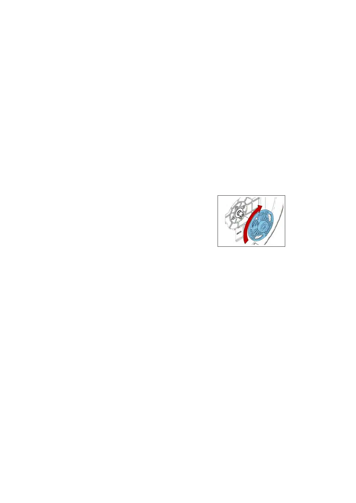
5.2.2 Brush Coupling Flange
• Put the machine in safe conditions.
• Disassemble the Brush Deck from
the machine (see section 5.2.4 at page 25).
• Unscrew the Coupling Flange rotat-
ing it in the same direction as the
brush in standard working condi-
tions (see fig. 5.2.2-15).
• Proceed at reverse to refit the part
being careful to lubricate the thread
in order to prevent blockings be-
cause of dirt or oxide.
5.2.2-15
5.2.3 Brush Motor
• Put the machine in safe conditions.
• Disassemble the Brush Deck from
the machine (see section 5.2.4 at page 25).
• Unscrew the Coupling Flange from
the motor shaft (see section 5.2.2 at page 24).
• Disconnect the water hose from the
motor (see fig. 5.2.3-16).
• Unscrew the 4 fixing screws and re-
move the motor (see fig. 5.2.3-17).
• Proceed at reverse to refit the part
(Use the thread lock liquid on the
screw during the assembling).
24