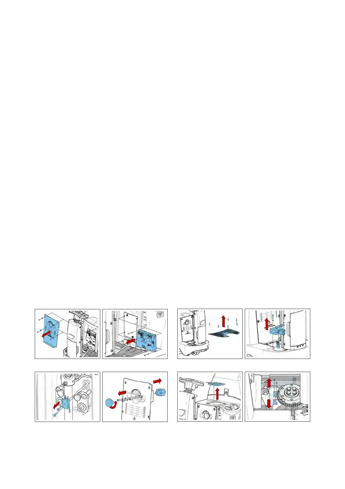
5.1.4 Microswitch
• Put the machine in safe conditions.
• Remove the screws that secure the
front carter to the steering column.
• Disconnect the wires connected to
the microswitch.
• To remove the microswitch, unscrew
the two screws and remove the de-
vice (see fig. 5.1.5-9).
5.1.5 Emergency Button
• Put the machine in safe conditions.
• Remove the screws to remove the
footrest.
• Remove the screws to remove the
electrical system cover.
• Disconnect the electrical wiring of
the emergency button.
• Remove the screws to remove the
emergency button from the carter (see
fig. 5.1.5-10).
5.1.5-7 5.1.5-8
5.1.5-9 5.1.5-10
5.1.6 Traction Pedal
• Put the machine in safe conditions.
• Remove the screws to remove the
footrest (see fig. 5.1.7-11).
• Release the footswitch connector
and unscrew the two screws holding
the pre-assembly pedal (see fig. 5.1.7-12).
• Remove the pedal.
5.1.7 Dead Man Switch (Seat
microswitch)
• Put the machine in safe conditions.
• Remove the seat from the machine
(see section 5.4.8 at page 32).
• Remove the switch connecting
joints.
• Remove the dead man Switch (see
fig. 5.1.7-13) (ATTENTION: The dead
man Switch is glued to the lubritene
spacer).
5.1.7-11 5.1.7-12
5.1.7-13 5.1.7-14
23