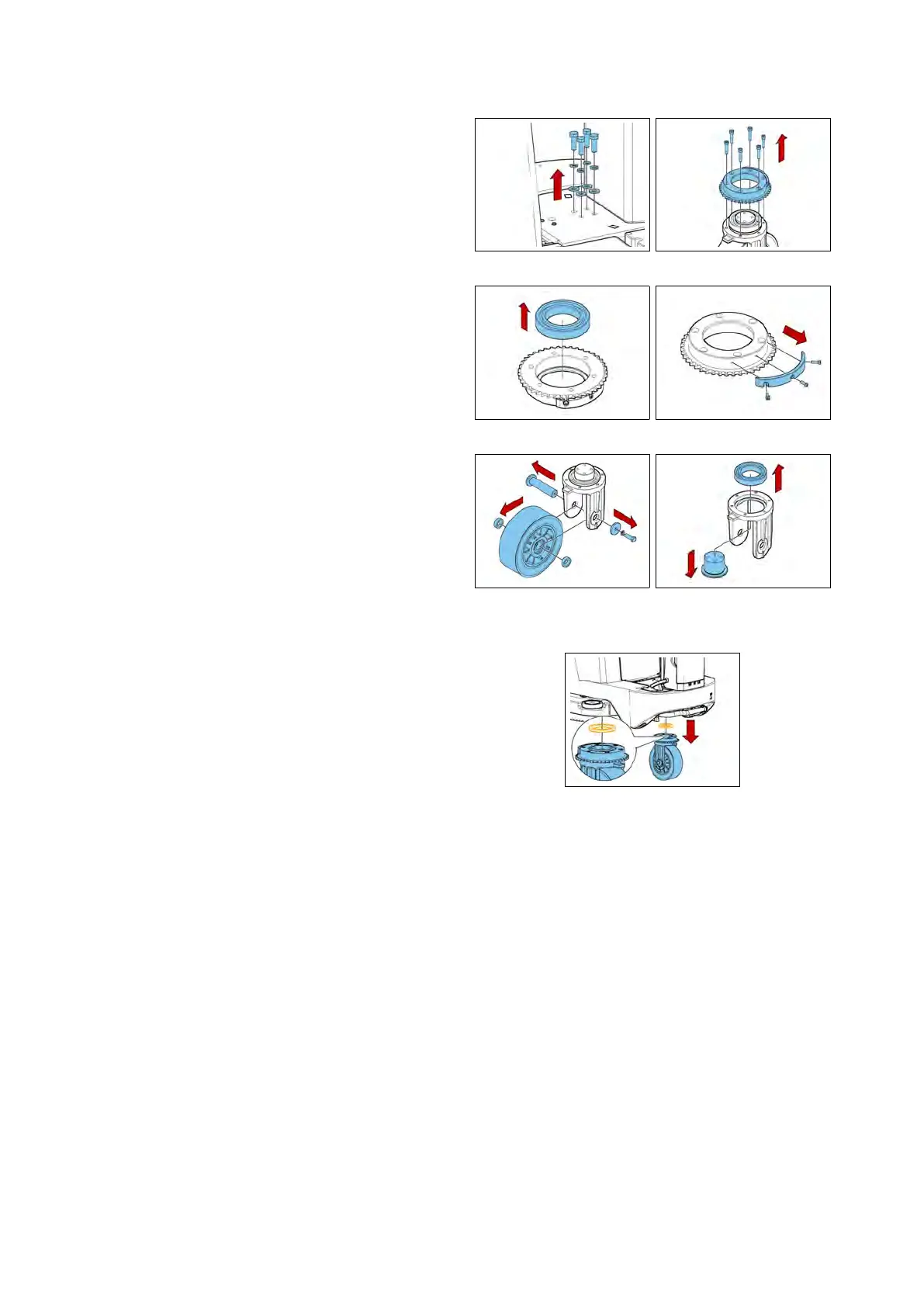
5.4.7 Sprocket of the wheel sup-
port bearings cam
• Put the machine in safe conditions.
• Remove the steering chain (see section
5.4.6 at page 31).
• Lift the front wheel off the ground.
• Remove the screws securing the
front wheel to the frame (see fig. 5.4.7-
62).
• Remove the sprocket fixing screws
(see fig. 5.4.7-63) (see fig. 5.4.7-64).
• Remove the sprocket.
• Remove the screws that secure the
cam to the sprocket and remove the
cam (see fig. 5.4.7-65).
• Remove the Front Wheel (see fig. 5.4.7-
66).
• Remove the bearings Pin and the
Bearings (see fig. 5.4.7-67).
• Proceed at reverse to refit the part.
ATTENTION: WHEN ASSEMBLING, PAY EX-
TREME ATTENTION AT THE CORRECT PO-
SITIONING OF THE SPACER 436224 (SEE
FIG. 5.4.7-68), BECAUSE IT IS FUNDAMENTAL
FOR THE PROPER FUNCTIONING OF THE
PAR T.
5.4.7-62 5.4.7-63
5.4.7-64 5.4.7-65
5.4.7-66 5.4.7-67
5.4.7-68
5.4.8 Seat
• Put the machine in safe conditions.
• Remove the screws to remove the
footrest.
• Unscrew the screws to remove the
electrical system cover (see fig. 5.4.8-69).
• Unscrew the lower screws that fix
the seat (see fig. 5.4.8-70).
• Lift the Recovery Tank and unscrew
the rear screws that fix the seat (see
fig. 5.4.8-71).
32