5.4 Frame and Traction
System
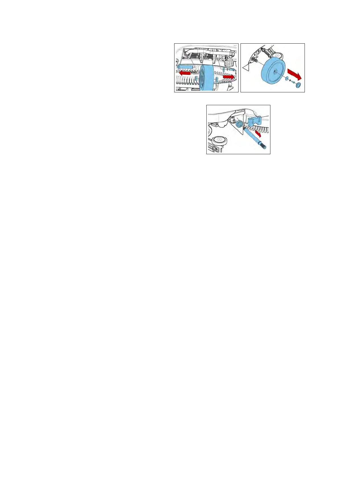
5.4.1 Front Wheel
• Put the machine in safe conditions.
• Lift up the front wheel from the
ground.
• Unscrew the fixing screw of the
wheel shaft to the support.
• Remove the wheel securing shaft to
the support (see fig. 5.4.2-46).
• Proceed at reverse to refit the part.
5.4.2 Rear Wheel
• Put the machine in safe conditions.
• Lift up the related rear wheel from
the ground.
• Remove the hub cap by levering with
a small flat screwdriver.
• Loosen the fixing bolt of the wheel to
the axle shaft (see fig. 5.4.2-47).
• Proceed at reverse to refit the wheel
(Use the thread lock liquid on the
screw during the assembling).
5.4.3 Drive shaft
• Put the machine in safe conditions.
• Remove the wheel connected to the
concerned axle (see section 5.4.2 at page 30).
• Remove the drive shaft from the
traction motor using, if necessary,
an extractor (see fig. 5.4.2-48).
• Proceed at reverse to refit the part.
5.4.2-46 5.4.2-47
5.4.2-48
5.4.4 Traction Gearmotor
• Put the machine in safe conditions.
• Remove the rear wheels (see section 5.4.2
at page 30).
• Remove the drive shafts from the
machine.
• Disconnect the electrical connector
of the Traction Gearmotor.
• Remove the screws securing the
Traction Gearmotor to the machine
frame (see fig. 5.4.4-53).
• Remove the traction gearmotor.
• Remove the brackets and bearing by
unscrewing the fixing screws (see fig.
5.4.4-54).
• Proceed at reverse to refit the part.
5.4.5 Steering shaft
• Put the machine in safe conditions.
• Remove the front carter from the
steering column by loosening the
screws.
• Loosen the upper dowels from the
universal joint (see fig. 5.4.5-55).
30